
Quick wear test device of engine valve seat ring

A technology for engine valve and wear test, which is used in measuring devices, testing of mechanical components, testing of machine/structural components, etc. It can solve the problem of long cycle time and high cost, improve design reliability, improve independent research and development capabilities, economical and Significant social benefits

Inactive Publication Date: 2015-05-20
海宁鼎丞智能设备有限公司
View PDF6 Cites 0 Cited by
  • Summary
  • Abstract
  • Description
  • Claims
  • Application Information

AI Technical Summary

Problems solved by technology

[0003] The present invention provides a rapid wear test device for engine valve seat rings, aiming at the problem of long period and high cost existing in the current engine valve and seat ring wear life test relying on the reliability bench of the whole machine.

Method used


Image

  • Quick wear test device of engine valve seat ring
  • Quick wear test device of engine valve seat ring

Examples


Embodiment Construction

[0013] The present invention will be further described below in conjunction with the drawings.

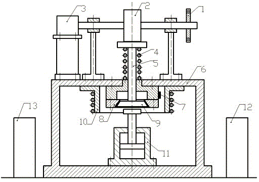
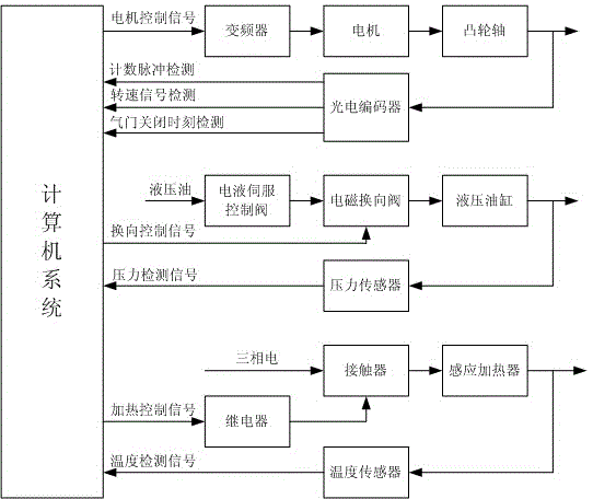
[0014] Such as figure 1 As shown, the simulation test device of the present invention consists of photoelectric encoder 1, camshaft 2, motor 3, valve spring 4, valve stem 5, frame 6, temperature sensor 7, seat ring 8, valve valve body 9, induction heater 10. It is composed of hydraulic cylinder 11, hydraulic control system 12, and test control system 13. The motor 3 drives the camshaft 2 to push the valve stem 5 to open the valve, and the valve seat is pushed by the restoring force of the valve spring 4. The shape, size and material of the cam, valve spring, seat ring, and valve body should be the same as those of the test piece. When the valve body 9 is seated, the hydraulic cylinder 11 rises, hits the bottom surface of the valve body 9 and applies a load, simulating the impact of the combustion pressure on the bottom surface of the valve body during actual engine operation. An ind...


PUM


Abstract

The invention relates to a quick wear test device of an engine valve seat ring. Evaluation of a wear life of the existing engine valve and seat ring is only completed by an overall reliability bench test at present, the period is long, and the expense is high. The quick wear test device is characterized in that a motor is arranged on a stander, wherein the motor is used for driving a cam shaft, the end of the motor is provided with a photoelectric coder, the top end of a valve rod is contacted with the cam shaft, and the bottom end of the valve rod stretches into the stander and provided with a valve body; and a seat ring which is matched with the valve body is arranged inside the stander, and the valve rod outside the stander is also provided with a valve spring. The bottom inside of the stander is provided with a hydraulic oil cylinder, and the position of the hydraulic oil cylinder is opposite to the valve body. The periphery of the valve seat ring is provided with a sensing heater, and the valve seat ring is also provided with a temperature sensor. The quick wear test device is used for researching a reliability design technology of an engine air distribution mechanism component and has important significance on improving the independence research and development capacity of air distribution mechanism component manufacturers in China and improving the overall design reliability of an engine.

Description

Technical field [0001] The invention belongs to the technical field of electromechanical integration, and relates to a rapid wear test device for an engine valve seat ring. Background technique [0002] The wear life of the engine valve and seat ring is directly related to the life of the engine. Therefore, it is urgent to study the wear of the valve and seat ring during the engine work process in the process of engine design and development. The engine valve seat ring rapid wear test device can be used to study the wear-resistant materials of the valve train, the working state of the valve, the failure mechanism of the valve, the valve wear life, etc., to form the wear design, test specifications and performance evaluation methods of the valve train components. The evaluation of the wear life of the valve and seat ring currently relies on the reliability of the complete machine bench test, which has a long cycle and high costs. It is difficult for valve and seat manufacturers t...

Claims


Application Information

Patent Timeline
Patent Type & Authority Patents(China)
IPC IPC(8): G01M13/00G01M7/08
Inventor 陈国金刘婷婷刘忠民彭章明朱泽飞元广杰苏少辉龚友平
Owner 海宁鼎丞智能设备有限公司
Learn More