
Drilling work-over platform power source mechanical-to-electrical device

A power source and platform technology, applied in electromechanical devices, electrical components, earthwork drilling and production, etc., can solve the problems of increasing operating costs of drilling and workover platforms, mechanical wear of high-power diesel engines, waste of lubricating oil, etc., and reduce labor intensity , Save equipment costs, reduce production costs

Inactive Publication Date: 2015-05-20
新疆派特罗尔能源服务股份有限公司
View PDF0 Cites 0 Cited by
  • Summary
  • Abstract
  • Description
  • Claims
  • Application Information

AI Technical Summary

Problems solved by technology

[0002] On the oil drilling and workover platform, the power source of the mechanical drilling rig is basically driven by the on-site diesel engine. In order to prolong the service life of the diesel engine, a valuable flexible buffer device (hydraulic torque converter or hydraulic Force coupling), with the implementation of the national energy saving and emission reduction project and the successful application of electric drilling rig grid power technology, in places where grid power is available, mechanical drilling rigs sometimes have to work under small loads or no-loads due to construction needs Only the driving of a high-power diesel engine can be used on the site. At this time, most or even all of the power generated by the diesel engine burning diesel is useless, which not only causes waste of energy (diesel), but also causes mechanical wear of the high-power diesel engine and maintenance of the diesel engine. Lubricating oil waste and environmental pollution
In addition, the expensive flexible buffer device at the power output end of the diesel engine, the hydraulic oil used, repair, maintenance, and maintenance personnel will increase the operating cost of the drilling and workover platform

Method used


Image

  • Drilling work-over platform power source mechanical-to-electrical device

Examples


Embodiment Construction

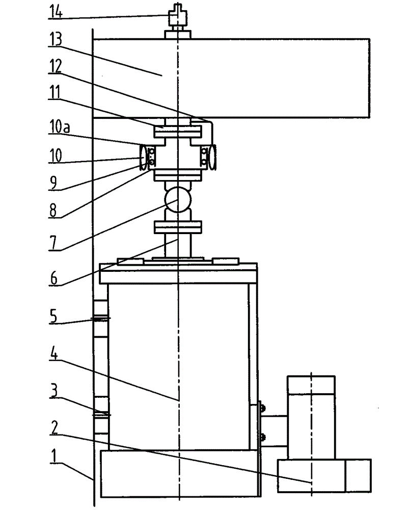
[0011] Such as figure 1 As shown, a power source machine-to-electric device for drilling and workover platform is mainly composed of base 1, cooling fan 2, bolt 3, AC frequency conversion motor 4, bolt 5, motor output flange 6, cardan shaft 7, clutch friction hub 8. Clutch empty sleeve bearing 9, clutch air bag 10, clutch shaft 10a, transmission box power input shaft flange 11, gas pipeline 12, transmission box 13 and air guiding faucet 14, AC variable frequency motor 4 is installed on the base 1, Use bolts 3 and 5 to fix the AC variable frequency motor 4 on the base 1. The AC variable frequency motor 4 is equipped with a cooling fan 2. The motor output flange 6 at the output end of the AC variable frequency motor 4 is connected to the cardan shaft 7. The cardan shaft 7 is connected with the clutch friction hub 8, and the clutch airbag 10 is fixed around the outer ring of the clutch shaft 10a. A clutch empty sleeve bearing 9 is embedded between the clutch shaft 10a and the clu...


PUM


Abstract

The invention discloses a drilling work-over platform power source mechanical-to-electrical device. The drilling work-over platform power source mechanical-to-electrical device is characterized in that an AC variable frequency motor is mounted on a base, and the motor is connected with a transmission case through a cardan shaft, a clutch and a flange; all the devices are assembled, adjusted and firmed, the axis centers of all the devices are basically located in the axis of the AC variable frequency motor and a transmission case power input shaft flange, the error does not exceed 2 mm, all bolts are fastened to fix all the devices, a cooling fan is started, the AC variable frequency motor is started after it is checked that the ventilation cooling function of the AC variable frequency motor is normal, a two-position three-way air switch of the clutch is switched on, compressed air enters a clutch air bag through an air pipeline to make the clutch air bag swell, a clutch friction plate on the inner ring of the clutch air bag is pushed to make close contact with a clutch friction hub so that the clutch friction plate and the clutch friction hub can be connected, and at the moment, power of the AC variable frequency motor is transmitted into the transmission case and output through a motor output flange, the cardan shaft, the clutch friction hub, a clutch shaft and the transmission case power input shaft flange.

Description

technical field [0001] The invention relates to changing the power source from a diesel engine to an AC variable frequency motor for direct drive in an oil drilling and workover platform. Background technique [0002] On the oil drilling and workover platform, the power source of the mechanical drilling rig is basically driven by the on-site diesel engine. In order to prolong the service life of the diesel engine, a valuable flexible buffer device (hydraulic torque converter or hydraulic Force coupling), with the implementation of the national energy saving and emission reduction project and the successful application of electric drilling rig grid power technology, in places where grid power is available, mechanical drilling rigs sometimes have to work under small loads or no-loads due to construction needs Only the driving of a high-power diesel engine can be used on the site. At this time, most or even all of the power generated by the diesel engine burning diesel is usele...

Claims


Application Information

Patent Timeline
Patent Type & Authority Applications(China)
IPC IPC(8): E21B41/00
CPCH02K7/108E21B41/00H02K7/1163
Inventor 张吉忠李东平霍鹏程家胜程丁山王芝霖孙丹李占春徐晓娟赵煊郑铁军张甫王俊李有力慕武
Owner 新疆派特罗尔能源服务股份有限公司
Learn More