Three-channel water-cooled air-cooled mixing device structure for computer cpu

A mixing device and three-channel technology, applied in circuits, electrical components, electric solid devices, etc., can solve the problems of small application range and unsuitable application occasions, and achieve the effect of large application range, small water pressure loss, and guaranteed cooling effect

Inactive Publication Date: 2016-03-30
WUXI FORMEN TECHN
View PDF5 Cites 0 Cited by
  • Summary
  • Abstract
  • Description
  • Claims
  • Application Information

AI Technical Summary

Problems solved by technology

[0002] The current computer CPU cooling generally adopts two methods of air cooling and water cooling. With the continuous development of graphics card processing chips, the heat generated during the work process continues to increase. In order to ensure good heat dissipation performance and normal operation of the graphics card, Its air cooling must be cooled by a high-speed fan. The high-speed fan brings loud noise and vibration, which is annoying.
However, in the existing water cooling mode, the cooling effect of the water cooling module can only reduce the temperature to the ambient temperature at most, which is not suitable for applications where the ambient temperature is relatively high, and its scope of application is small

Method used


Image

  • Three-channel water-cooled air-cooled mixing device structure for computer cpu
  • Three-channel water-cooled air-cooled mixing device structure for computer cpu

Examples


Embodiment Construction

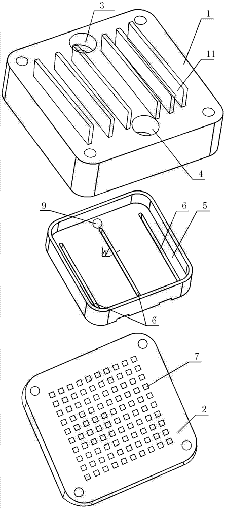
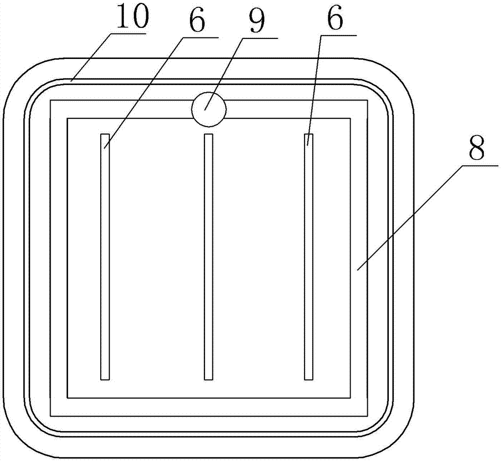
[0008] See figure 1 , figure 2 , which includes an upper cover plate 1, a micro-cutting cooling plate 2, the upper end surface of the upper cover plate 1 is provided with a water outlet 3, a water inlet 4, the upper cover plate 1 is mounted on the micro-cutting cooling plate 2, the upper cover plate 1, the micro-cutting cooling plate The cavity formed by cutting the cooling plate 2 is provided with a jet diverter plate 5, and the jet diverter plate 5 is provided with three parallel flow channel notches 6, the middle flow channel notch 6 is located directly below the water inlet 3, and the flow channel notches 6 on both sides are The flow channel notch 6 is located on both sides of the middle flow channel notch 6, the aperture of the water inlet 3 is larger than the width W of the middle flow channel notch 6, and the water inlet 4 is respectively connected to three outlets along the upper surface of the jet splitter plate 5. Parallel runner slots 6, the bottom of the runner s...


PUM


Abstract

The invention provides a three-runner water-cooling and air-cooling hybrid device structure for a computer CPU (central processing unit). The three-runner water-cooling and air-cooling hybrid device structure can cool heated devices to be lower than the ambient temperature so as to be applicable to various environments, wide in application range, quiet and free of noise. The three-runner water-cooling and air-cooling hybrid device structure comprises an upper cover plate and a micro-cut cooling plate, the upper end face of the upper cover plate is provided with a water outlet and a water inlet, and the upper cover plate covers the micro-cut cooling plate. The three-runner water-cooling and air-cooling hybrid device structure is characterized in that a jet flow distribution plate is arranged in a hollow cavity formed by the upper cover plate and the micro-cut cooling plate and provided with three parallel runner notches, the middle runner notch is positioned under the water inlet, the runner notches on two sides are positioned on two sides of the middle runner notches, and the diameter of the water inlet is larger than the width of the middle runner notch.

Description

technical field [0001] The invention relates to the technical field of computer CPU cooling, in particular to the structure of a three-channel water-cooling and air-cooling mixing device for a computer CPU. Background technique [0002] The current computer CPU cooling generally adopts two methods of air cooling and water cooling. With the continuous development of graphics card processing chips, the heat generated during the work process continues to increase. In order to ensure good heat dissipation performance and normal operation of the graphics card, Its air cooling must be cooled by a high-speed fan, which brings loud noise and vibration, which is annoying. However, in the existing water-cooling cooling method, the cooling effect of the water-cooling module can only reduce the temperature to the ambient temperature at most, which is not suitable for applications where the ambient temperature is relatively high, and its applicable range is small. Contents of the inven...

Claims


Application Information

Patent Timeline
Patent Type & Authority Patents(China)
IPC IPC(8): H01L23/473H01L23/467G06F1/20
Inventor 谈士权
Owner WUXI FORMEN TECHN
Why Eureka
Try Eureka