Metal component coupling structure and device

A technology for metal parts and connecting structures, applied in the field of connecting structures and connecting devices of metal parts, can solve the problems of poor productivity, increased weight and cost of parts, etc., and achieve the effect of high connection strength and high precision connection

Active Publication Date: 2012-12-19
KEIHIN SEIMITSU IND
View PDF8 Cites 2 Cited by
  • Summary
  • Abstract
  • Description
  • Claims
  • Application Information

AI Technical Summary

Problems solved by technology

However, the weight and cost of components increase to form the bracket
In addition, productivity deteriorates due to tightening of bolts in mass production

Method used


Image

  • Metal component coupling structure and device
  • Metal component coupling structure and device
  • Metal component coupling structure and device

Examples


Embodiment Construction

[0047] Hereinafter, embodiments of the present invention will be described with reference to the drawings.

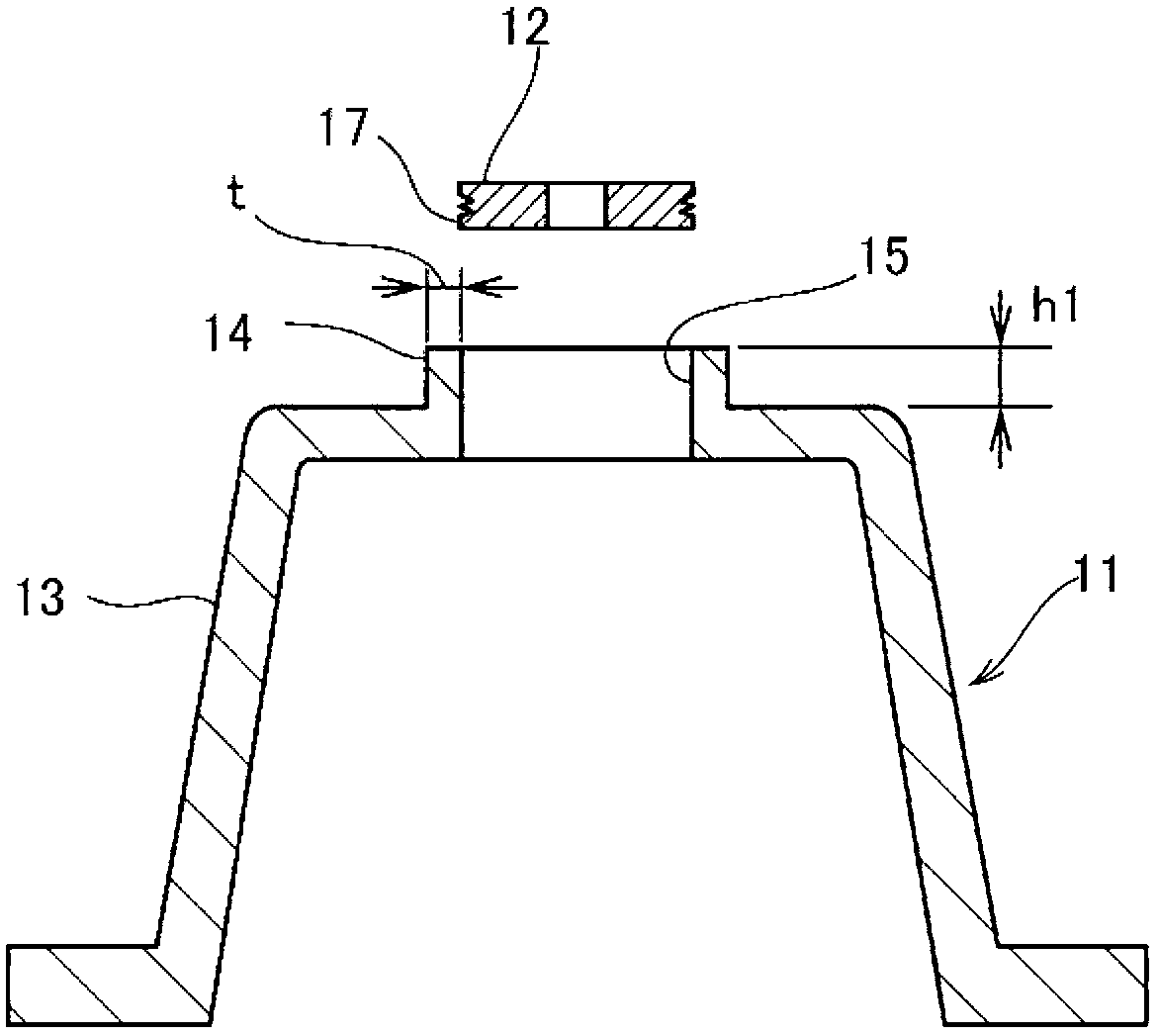
[0048] FIG. 1 shows an example of a first metal member 11 and a second metal member 12 to which the metal member connection structure according to this embodiment can be applied. In addition, the shapes of the first metal member 11 and the second metal member 12 shown in the drawings in this embodiment are merely examples for explaining this embodiment, and the applied parts of this embodiment are not limited to these shapes. .

[0049] The first metal component 11 is a metal frame, and includes: a main body 13 and an annular portion 14 integrally formed with the main body 13 . The opening 15 is formed in the annular portion 14 which is, for example, a thin portion having a thickness t of 3 mm and a height h1 of 6 mm. The first metal component 11 is a molded die-cast product made of aluminum alloy or the like, which is also a material that lacks ductility.

[0050] T...


PUM

PropertyMeasurementUnit
thicknessaaaaaaaaaa
thicknessaaaaaaaaaa
heightaaaaaaaaaa

Abstract

Disclosed is a metal component coupling structure and metal component coupling device capable of high strength and high precision coupling. An axial part (17) of a second metal component (12) is fitted in an annular part (14) of a first metal component (11), a restraint ring (33) is arranged on the outer circumference of the annular part (14) of the first metal component (11), and, by plastically deforming by applying force to the annular part (14), said annular part (14) is made to enter into a coupling groove (16) of the axial part (17), coupling the first metal component (11) and the second metal component (12) by mechanical interlocking.

Description

technical field [0001] The present invention relates to a connection structure and a connection device of metal parts connected by plastic flow. Background technique [0002] Conventionally, in order to fit and fix the shaft-shaped metal member to the ring-shaped portion of the frame made of metal, an integrated bracket portion is formed along the outer peripheral edge of the shaft-shaped metal member, and the bracket portion is fastened with bolts. on the rack. However, the weight and cost of components increase to form the bracket portion. In addition, productivity deteriorates due to fastening of bolts in mass production. Therefore, a method of plastically deforming and connecting metals is known (for example, refer to Patent Document 1). [0003] prior art literature [0004] Patent Document 1: Japanese Patent Application Laid-Open No. 5-318109 Contents of the invention [0005] However, in the connection of metal parts using plastic flow connection, in order to o...

Claims


Application Information

Patent Timeline
Patent Type & Authority Applications(China)
IPC IPC(8): B21D39/00
CPCB23P11/00B21K25/00B21D39/06Y10T403/4949B21D39/031B21D39/037
Inventor 川目信幸村上硕哉
Owner KEIHIN SEIMITSU IND
Why Eureka
Try Eureka