Multi-groove circulating silicon wafer cleaning machine

A technology for cleaning silicon wafers and cleaning tanks, applied in cleaning methods and appliances, cleaning methods using liquids, chemical instruments and methods, etc., can solve the problem that overflow liquid cannot be recycled, increase the production cost of silicon wafers, and frequent cleaning tanks Change water and other issues to achieve the effect of reducing liquid pollution, reducing water consumption, and reducing production costs

Active Publication Date: 2012-12-26
晶海洋半导体材料(东海)有限公司
View PDF9 Cites 10 Cited by
  • Summary
  • Abstract
  • Description
  • Claims
  • Application Information

AI Technical Summary

Problems solved by technology

[0004] The existing 7-tank cleaning machine has the following defects: the cleaning method is very limited, and the 7 cleaning tanks are arranged in sequence, of which, the 3rd and 4th tanks are generally fixed medicine tanks (the silicon wafers are cleaned with liquid medicine), and the cleaning tanks are sequentially arranged. Among the 7 cleaning tanks arranged in the second order, the water in the rear tank body will be cleaner than the water in the front tank body. However, because the 3-4 tanks are equipped with liquid medicine for blocking, the pollution rate of t...

Method used


Image

  • Multi-groove circulating silicon wafer cleaning machine

Examples


Embodiment 1

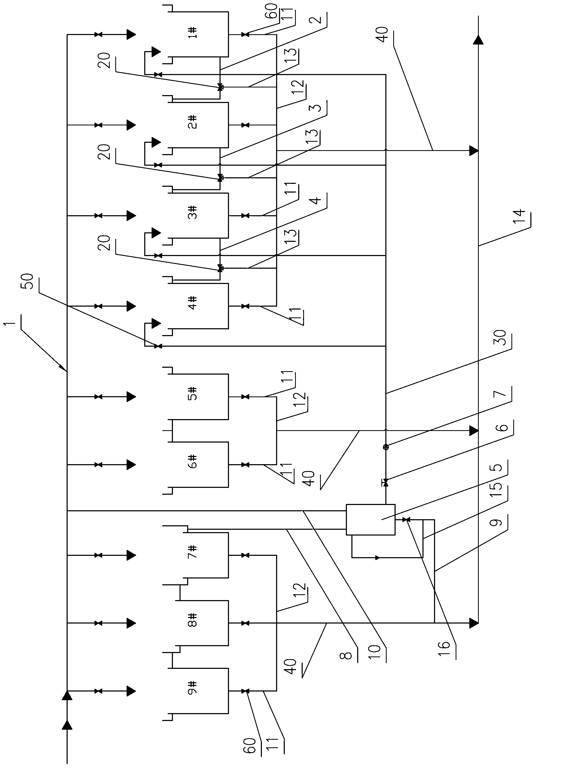
[0029] Such as figure 1Shown is a multi-groove ultrasonic circulation silicon wafer cleaning machine of the present invention, including a cuboid casing, a cleaning tank arranged in the casing, a water supply pipeline 1 for providing pure water for the cleaning tank, and a The drainage pipeline for the discharge of the cleaning liquid in the cleaning tank. In this embodiment, the cleaning tank is 9 sequentially arranged tanks, mainly composed of dual-function cleaning tanks (No. 1-4 Cleaning tank 1#-4#), chemical cleaning tank for alkaline cleaning with liquid medicine (the fifth cleaning tank 5#, sixth cleaning tank 6#), water washing cleaning tank for pure water cleaning (the seventh cleaning tank 7 #, the 8th cleaning tank 8# and the 9th cleaning tank 9#), among them, the water washing cleaning tank (the 9th cleaning tank 9#) in the last order is the slow lifting pre-elution tank, and the 1st-4th cleaning tank Between two adjacent tanks, there is an overflow pipe that comm...

Embodiment 2

[0044] The difference between this embodiment and Embodiment 1 is that there are 6 cleaning tanks, of which, there are 2 dual-function cleaning tanks, which are the first and second cleaning tanks, and 2 chemical cleaning tanks, which are the third cleaning tanks. , 4 cleaning tanks, there are 2 washing tanks, which are the 5th and 6th cleaning tanks, and the slow pre-elution tank is the 6th cleaning tank.

Embodiment 3

[0046] The difference between this embodiment and Embodiment 1 is that there are 12 cleaning tanks, among which, there are 5 dual-function cleaning tanks, which are the 1st to 5th cleaning tanks, and 3 cleaning tanks, which are the 6th cleaning tanks. -8 cleaning tanks, there are 4 washing tanks, which are the 9th to 12th cleaning tanks, and the slow lifting pre-elution water tank is the 12th cleaning tank.


PUM


Abstract

The invention discloses a multi-groove circulating silicon wafer cleaning machine which comprises a machine shell, cleaning grooves, a water-supplying pipeline, and water-exhausting pipelines, wherein the cleaning grooves are at least groove bodies which are sequentially arranged. The groove bodies are sequentially composed of at least two difunctional cleaning grooves, at least two medicine-washing cleaning grooves, and at least two water-washing cleaning grooves which are of slow-lifting prewashing dewatering grooves. The difunctional cleaning grooves are used for pure water cleaning or medical liquid alkali cleaning, the medicine-washing cleaning grooves are used for medical liquid alkali cleaning, and the water-washing cleaning grooves are used for pure water cleaning. Overflowing pipes which are arranged between two adjacent groove bodies of the difunctional cleaning grooves are communicated with the groove bodies, and reverse sequence overflowing of the difunctional cleaning grooves is formed by the overflowing pipes. The water-exhausting pipes are connected with the overflowing pipes through tee joint valves, so that overflowing liquid can flow into a lower-level groove body or exhaust through the water-exhausting pipes, and thereby the difunctional cleaning grooves achieve dual functions of pure water cleaning and medical liquid alkali cleaning. The difunctional cleaning grooves of the multi-groove circulating silicon wafer cleaning machine can not only be used as alkali-cleaning grooves, but only can be used as water-washing grooves, facilitate adjusting and arranging of a silicon wafer cleaning working procedure, reduce water consumption through an overflowing manner, and save water resources.

Description

technical field [0001] The invention relates to a silicon chip cleaning machine, in particular to a multi-groove circulating silicon chip cleaning machine. Background technique [0002] In the production process of silicon wafers, in order to obtain good quality silicon wafers, it is required that the amount of impurities attached to the surface of the silicon wafers is extremely small. Therefore, the cut silicon wafers need to be cleaned. [0003] At present, the cleaning equipment used is a 7-tank cleaning machine. The 7-tank cleaning machine includes a casing, a cleaning tank installed in the casing, an ultrasonic device, a water supply pipeline for providing pure water, and a drainage pipeline for discharging cleaning liquid. Generally there are 7 and their functions are fixed. When the 7-tank cleaning machine is in operation, the transfer manipulator will put the cleaning baskets containing silicon wafers into 7 cleaning tanks for processing in sequence. Dry process a...

Claims


Application Information

Patent Timeline
IPC IPC(8): B08B3/12
Inventor 颜颉颃贾永前张欣
Owner 晶海洋半导体材料(东海)有限公司
Why Eureka
Try Eureka