
Steel plate stacker crane

A palletizer and steel plate technology, which is applied to metal processing equipment, feeding devices, manufacturing tools, etc., can solve the problems of difficult maintenance, low efficiency, time-consuming and laborious maintenance of palletizers, and achieve the improvement of the overall technical level and the convenience of installation and maintenance. , the effect of expanding the scope of use

Active Publication Date: 2014-07-30
TAIAN HUALU METALFORMING MACHINE TOOL
View PDF5 Cites 0 Cited by
  • Summary
  • Abstract
  • Description
  • Claims
  • Application Information

AI Technical Summary

Problems solved by technology

[0002] At present, the palletizers used in the steel coil Kaiping production line at home and abroad adopt the integral push-pull or integral slider structure. This structure has a single function and can only realize the stacking function. When the sheets are stacked and packed, the machine needs to be stopped. , after removing the stacked steel plates to make room for the next batch of work, the efficiency is low, and the mechanism is huge and cumbersome. It is difficult to guarantee the straightness and accuracy during manufacturing and processing, and the requirements for processing equipment are also high. Ordinary processing equipment It cannot be manufactured, and a large boring and milling machine must be used, and the manufacturing cost is very high; similarly, the maintenance of this kind of palletizer is even more difficult, time-consuming and laborious, which seriously affects normal production
Therefore, the supporting use of this kind of palletizer also seriously affects the advancement of the steel plate Kaiping production line.

Method used


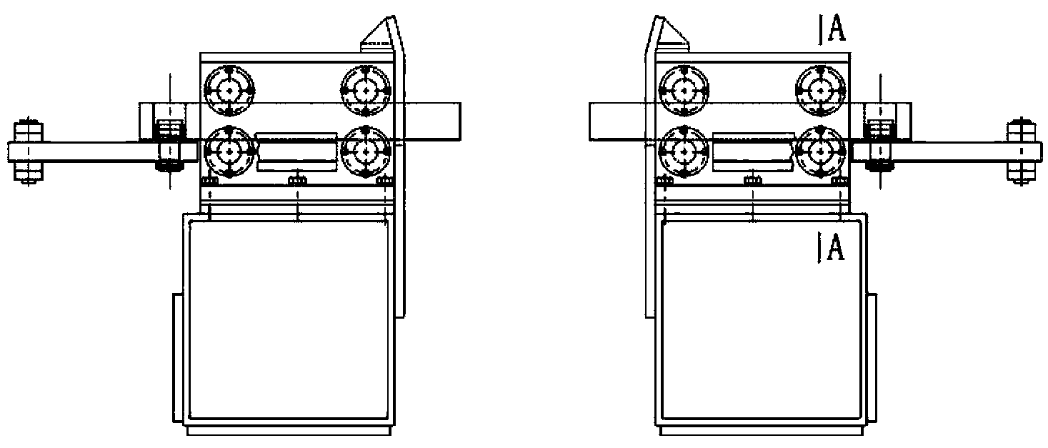
Image

  • Steel plate stacker crane
  • Steel plate stacker crane
  • Steel plate stacker crane

Examples


Embodiment Construction

[0015] Below in conjunction with accompanying drawing and embodiment the present invention is further described:

[0016] In the accompanying drawings, the components are numbered as follows:

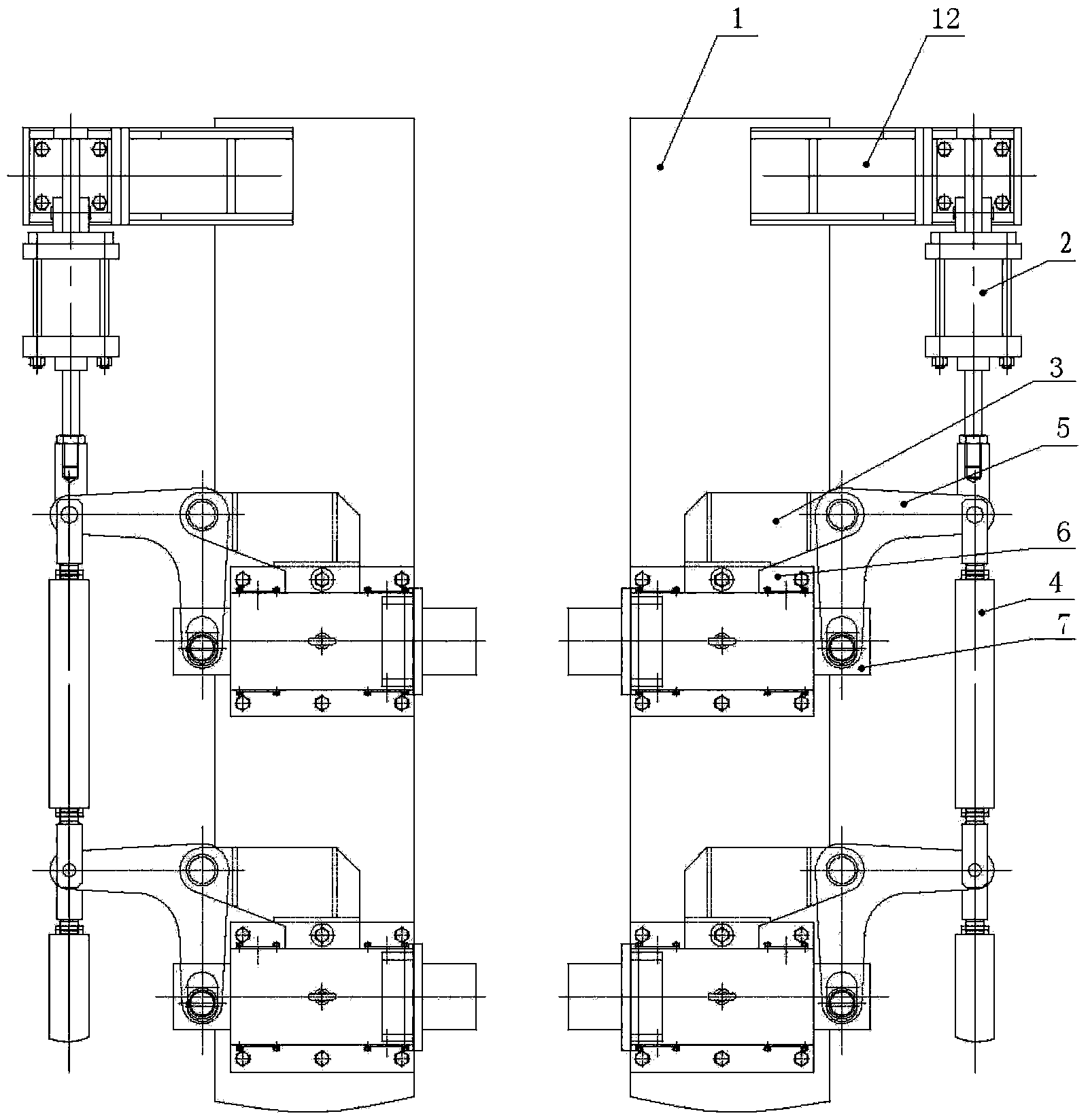
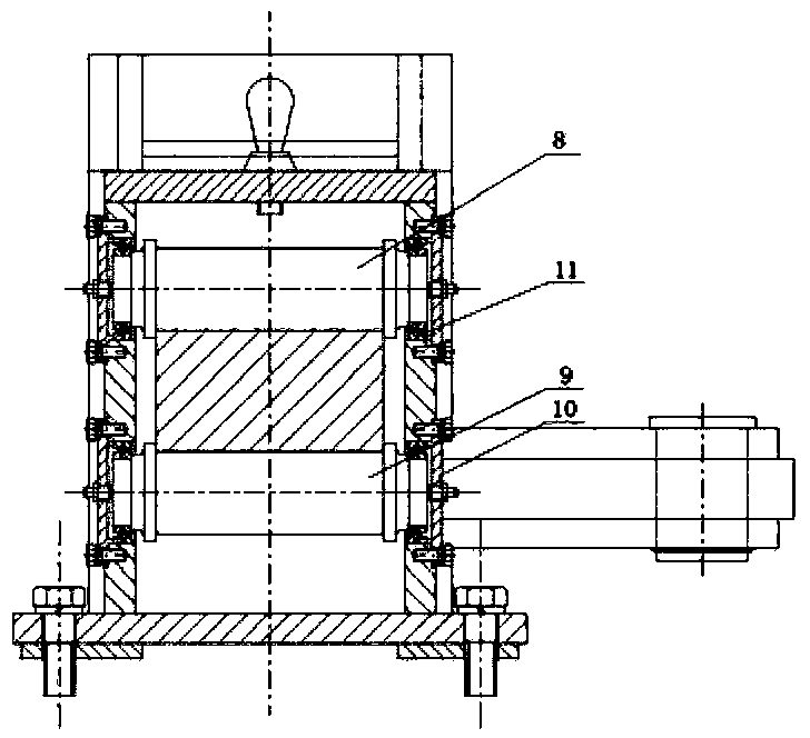
[0017] Fixed beam 1, cylinder 2, fixed earring 3, pull rod 4, swing rod 5, fixed support 6, slider 7, upper row of rollers 8, lower row of rollers 9, gland 10, rolling bearing 11, pillar 12.

[0018] Such as figure 1 , 2 Shown: a steel plate palletizer, including two parallel fixed beams 1 of equal length, a cylinder 2 is installed at one end of the fixed beam 1 through a pillar 12, and a plurality of fixed supports 6 are installed on the fixed beam 1; The upper row of rollers 8 and the lower row of rollers 9 are installed in the inner cavity of the support 6, and the shaft ends of the upper row of rollers 8 and the lower row of rollers 9 are equipped with rolling bearings 11, and the outside of the rolling bearings 11 is connected together by a gland 10 and a fixed support 6; The sl...


PUM


Abstract

The invention relates to a steel plate stacker crane which comprises two parallel fixed beams with equal lengths. A cylinder is fixed at one end of each fixed beam by a strut; a plurality of fixed supports are arranged on the upper surface of each fixed beam; upper row rollers and lower row rollers are arranged in inner cavities of the fixed supports; the shaft ends of the upper row rollers and the lower row rollers are provided with rolling bearings; the outsides of the rolling bearings are connected with the fixed supports by glands; sliding blocks are arranged between the upper row rollers and the lower row rollers; a fixed lug ring is arranged on one side of each fixed support; swing rods are hinged with the fixed lug rings by hinge pins; both ends of the swing rods are respectively provided with round holes; one ends of the swing rods are movably connected with the sliding blocks; the other ends of the swing rods are movably connected with pull rods; and a plurality of pull rods are connected end to end and then are connected on piston rods of the cylinders. According to the invention, a plurality of split sliding block mechanisms are adopted; in a non-stop state, not only can the neat stacking of plates be implemented, but also a receiving function is added; due to the adoption of the split structure, the processing difficulty is reduced and the cost is reduced; the steel plate stacker crane is convenient to install and maintain; and the integral technical level of a coil opening production line is greatly promoted.

Description

technical field [0001] The invention relates to a steel plate palletizer used in a steel coil Kaiping production line, in particular to a steel plate palletizer which can be used when the production line does not stop running. Background technique [0002] At present, the palletizers used in the steel coil Kaiping production line at home and abroad adopt the integral push-pull or integral slider structure. This structure has a single function and can only realize the stacking function. When the sheets are stacked and packed, the machine needs to be stopped. , after removing the stacked steel plates to make room for the next batch of work, the efficiency is low, and the mechanism is huge and cumbersome. It is difficult to guarantee the straightness and accuracy during manufacturing and processing, and the requirements for processing equipment are also high. Ordinary processing equipment It cannot be manufactured, and a large boring and milling machine must be used, and the ma...

Claims


Application Information

Patent Timeline
Patent Type & Authority Patents(China)
IPC IPC(8): B21D43/22
Inventor 樊有平常欣左光胜
Owner TAIAN HUALU METALFORMING MACHINE TOOL
Learn More