Sidelight type backlight module and display device

A backlight module and side-light technology, which is applied in the field of backlight, can solve the problems of poor uniformity of light distribution, reduction of light quantity, small reflectivity, etc., and achieve the effect of uniform brightness of backlight and improvement of uniformity

Inactive Publication Date: 2012-12-26
BOE TECH GRP CO LTD +1
View PDF9 Cites 10 Cited by
  • Summary
  • Abstract
  • Description
  • Claims
  • Application Information

AI Technical Summary

Problems solved by technology

[0004] The above-mentioned liquid crystal display device inevitably has the following problems in practical applications, that is, since the LED lamp 2 is a point light source, the distribution of light incident on the light guide plate 1 is uneven, that is, when the light output by the LED lamp 2 irradiates on the input On the light surface, the difference between the light quantity incident on the area corresponding to the LED lamp 2 on the light incident surface and the light quantity corresponding to the interval area between two adjacent LED lamps 2 (hereinafter referred to as the interval area) on the light incident surface difference between
Moreover, since the reflectivity of the light incident surface of the light guide plate 1 is small, when the light output by the LED lamp 2 irradiates the light incident surface, the amount of reflected light 12 formed on the light incident surface is small, resulting in The quantity of light reflected twice by the surface of the base 4 opposite to the light incident surface is reduced, so that the quantity of light re-irradiated to the light incident surface, especially the interval area of ​​the light incident surface is also correspondingly reduced
In this case, the uniformity of light distribution incident on the light guide plate 1 is poor, so that the backlight of the liquid crystal panel is uneven (that is, the hotspot phenomenon occurs).

Method used


Image

  • Sidelight type backlight module and display device
  • Sidelight type backlight module and display device
  • Sidelight type backlight module and display device

Examples


Embodiment Construction

[0027] In order to enable those skilled in the art to better understand the technical solutions of the present invention, the edge-lit backlight module and the display device provided by the embodiments of the present invention will be described in detail below with reference to the accompanying drawings.

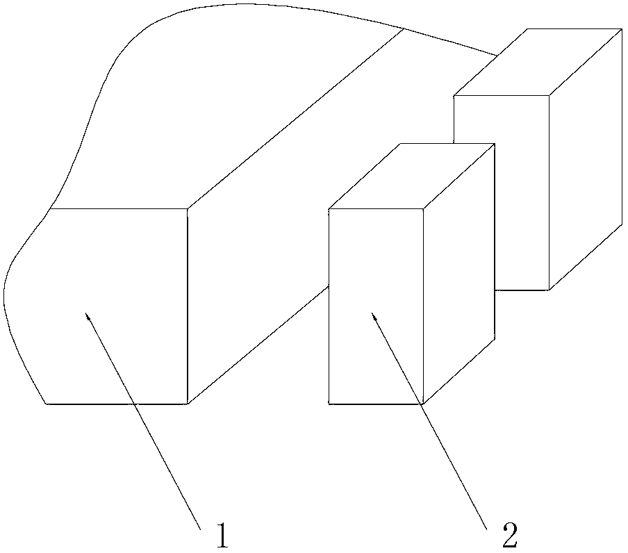
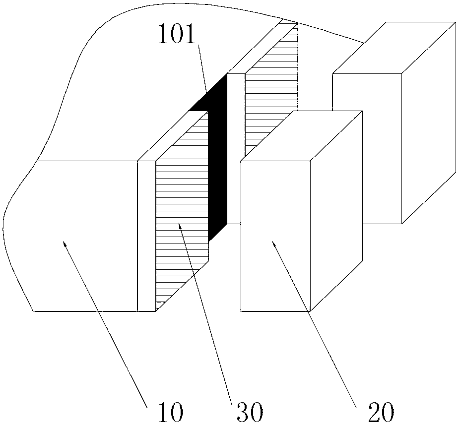
[0028] image 3 It is a schematic diagram of the structure of the edge-lit backlight module provided by the first embodiment of the present invention. See image 3 , The edge-lit backlight module includes a point light source driving base (not shown in the figure), a plurality of point light sources 20 and a light guide plate 10. The point light source 20 is installed on the point light source driving base to output light to the light guide plate 10; the light guide plate 10 is arranged opposite to the point light source 20 to convert the point light output by the point light source 20 into surface light and then spread out. In addition, the light guide plate 10 includes a lig...


PUM

PropertyMeasurementUnit
reflectanceaaaaaaaaaa

Abstract

The invention provides a sidelight type backlight module and a display device, and the sidelight type backlight module includes a plurality of point light sources, a point light source drive base, a light guide plate and a plurality of optical films, wherein the point light sources are mounted on the point light source drive base; the light guide plate includes an incident light surface opposite to the emergent light side of the point light sources; the optical films are arranged on the incident light surface, and the reflectivity of the optical films is larger than that of the incident light surface; and by dint of the optical films, the amount of light entering areas, corresponding to the point light sources, of the light guide plate, and the amount of light entering an interval area, between every two adjacent point light sources, of the light guide plate, become uniform, so that the uniformity of distribution of light entering the light guide plate can be improved, and further the backlight brightness of a liquid crystal display panel is uniform.

Description

Technical field [0001] The present invention relates to the technical field of backlight sources, in particular to an edge-lit backlight module and a display device. Background technique [0002] In the flat panel display technology, the liquid crystal display device is more and more widely used due to its advantages of low power consumption, relatively low manufacturing cost, and no radiation. [0003] The liquid crystal display device includes a liquid crystal panel and an edge-light backlight module. The edge-light backlight module is used to provide a light source to the liquid crystal panel so that the liquid crystal panel can output images. figure 1 It is a schematic diagram of the structure of an existing edge-lit backlight module. See figure 1 The existing edge-lit backlight module includes a light guide plate (LGP) 1, a point light source, and a point light source driving base. Among them, the point light source includes a plurality of light emitting diode (Light Emitting...

Claims


Application Information

Patent Timeline
Patent Type & Authority Applications(China)
IPC IPC(8): F21S8/00F21V13/00G02F1/13357F21Y101/02
Inventor 张宇陈秀云孙文佳
Owner BOE TECH GRP CO LTD
Why Eureka
Try Eureka