
Constant current driver of light emitting diode

A light-emitting diode and constant-current driver technology, which is applied in the field of light-emitting diode constant-current drivers, can solve the problems of single-stage PFC circuit power factor reduction, large reference signal error, and large current signal error, so as to reduce input errors and Effect of small current ripple and improved power factor

Inactive Publication Date: 2012-12-26
THINKLUX (ZHEJIANG) LIGHTING TECH CO LTD
View PDF4 Cites 11 Cited by
  • Summary
  • Abstract
  • Description
  • Claims
  • Application Information

AI Technical Summary

Problems solved by technology

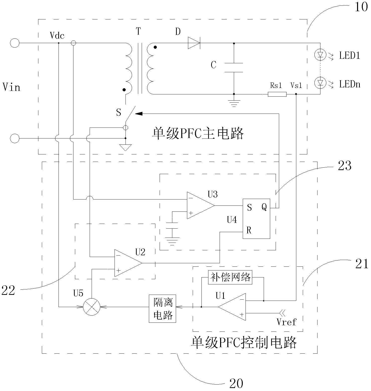
[0006] However, since there are ripples in the current signal output by the single-stage PFC circuit, and when the output current ripple is large, at this time, the error of the output current signal of the single-stage PFC main circuit is relatively large, so after passing through the current closed-loop control circuit There is a large error in the output signal, because the reference signal of the current control circuit 22 is obtained by multiplying the output signal of the current closed-loop control circuit 21 with the voltage sampling signal of the input terminal of the single-stage PFC main circuit through the multiplier, therefore, the current There is a large error in the reference signal of the control circuit 22
And the current control circuit 22 makes the current at the input end of the single-stage PFC circuit change following the variation of the reference signal of the current control circuit. Since there is a large error in the reference reference signal, the current at the input end of the single-stage PFC circuit has a large error. Large error, cannot accurately follow the change of the input voltage of the single-stage PFC circuit, so the power factor of the single-stage PFC circuit is greatly reduced

Method used


Image

  • Constant current driver of light emitting diode
  • Constant current driver of light emitting diode
  • Constant current driver of light emitting diode

Examples


Embodiment Construction

[0030] In order to enable those skilled in the art to better understand the solution of the present invention, the present invention will be further described in detail below with reference to the accompanying drawings and embodiments.

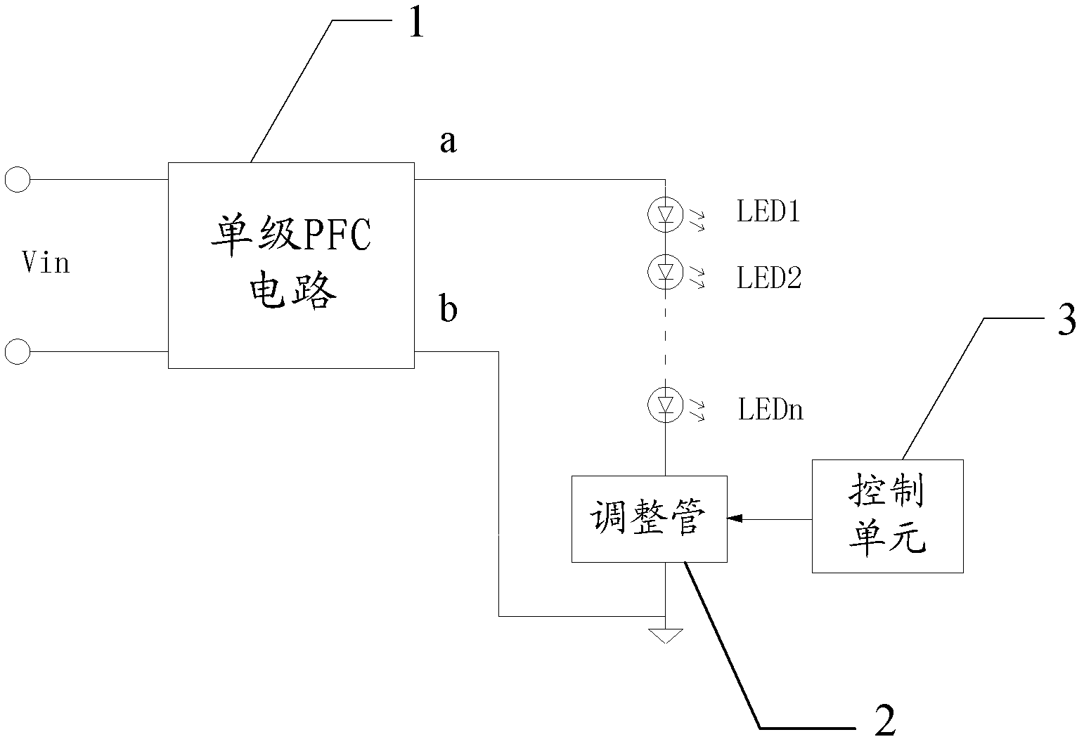
[0031] See figure 2 , Shows a schematic structural diagram of an LED constant current driving device according to an embodiment of the present invention, which mainly includes: a single-stage PFC circuit 1 composed of a single-stage PFC main circuit and a single-stage PFC control circuit, a regulator tube 2 and a control unit 3. among them:

[0032] The input terminal of the single-stage PFC circuit 1 is connected to the power supply Vin, the series branch of the regulator tube 2 and the LED load is connected between the two output terminals of the single-stage PFC circuit, and the control unit 3 is connected to the control terminal of the regulator tube 2 .

[0033] The single-stage PFC circuit can pass figure 1 The implementation of the circuit s...


PUM


Abstract

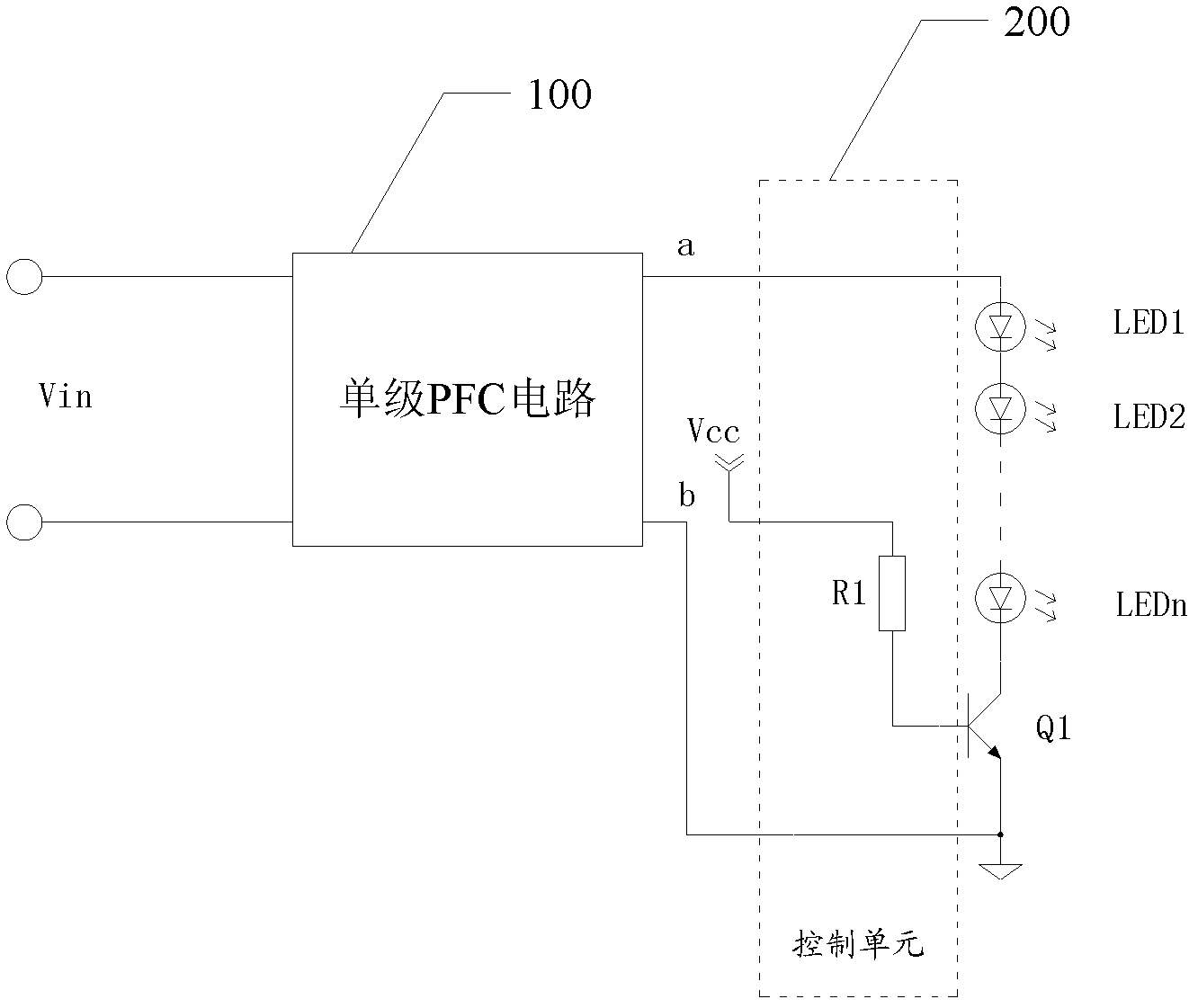
The invention discloses a constant current driver of a light emitting diode. The constant current driver comprises a single stage PFC (power factor correction) circuit, an adjusting tube and a control unit, wherein an input end of the single stage PFC circuit is connected with a power supply; the light emitting diode and the adjusting tube are connected in series between a first output end and a second output end; the anode of the LED is connected with the first output end; the cathode is connected with a first end of the adjusting tube; a second end of the adjusting tube is connected with the second output end of the single stage PFC circuit; the control end is connected with the control unit; the control unit can control the current flowing through the adjusting tube to be stabilized, so that the load characteristic of the connection of the single stage PFC circuit is changed, a load current wave of the single stage PFC circuit is reduced, so the error that output signals of the single stage PFC circuit are fed back to an input end of a closed control circuit is reduced, the error of a reference signal of a current control input end in the single stage PFC circuit is reduced as well, and power factors of the single stage PFC circuit are increased ultimately.

Description

Technical field [0001] The present invention relates to the technical field of constant current driving, in particular to a constant current driver for light emitting diodes. Background technique [0002] A constant current driver for a low-power LED (Light Emitting Diode) load usually uses a single-stage PFC (Power Factor Correction, power factor correction) circuit. The single-stage PFC circuit integrates the PFC circuit and the LED drive circuit into one Level circuit. [0003] Single-stage PFC circuit, in order to meet the relatively high power factor under heavy load conditions, the loop bandwidth is very low, the loop speed is very slow, therefore, the low frequency ripple of the output voltage is large, and the UI curve of the LED load is relatively high. Steep, and the UI curves of LEDs from different manufacturers are very different, that is, when the voltage across the LED lamp changes slightly, the current flowing through the LED lamp will change greatly, causing the LE...

Claims


Application Information

Patent Timeline
IPC IPC(8): H05B37/02H02M1/42
CPCY02B70/126Y02B70/10
Inventor 韩雪强吴莲
Owner THINKLUX (ZHEJIANG) LIGHTING TECH CO LTD
Learn More