Radio excitation system, detection method and electric vehicle

An excitation system and radio technology, applied in the direction of electronic commutation motor control, control system, motor control, etc., can solve the problems of inconvenient fault judgment, difficult to detect electrical parameters again, and achieve the effect of easy fault judgment.

Pending Publication Date: 2022-02-25
HUAWEI TECH CO LTD
View PDF7 Cites 2 Cited by
  • Summary
  • Abstract
  • Description
  • Claims
  • Application Information

AI Technical Summary

Problems solved by technology

[0004] However, due to the influence of factors such as parameter deviation and installation error of the excitation transformer, the actual electrical parameters may change, and when the electric excitation motor and the excitation transformer are assembled, it is difficult to detect the electrical parameters again, which is inconvenient for fault judgment

Method used


Image

  • Radio excitation system, detection method and electric vehicle
  • Radio excitation system, detection method and electric vehicle
  • Radio excitation system, detection method and electric vehicle

Examples


Embodiment 1

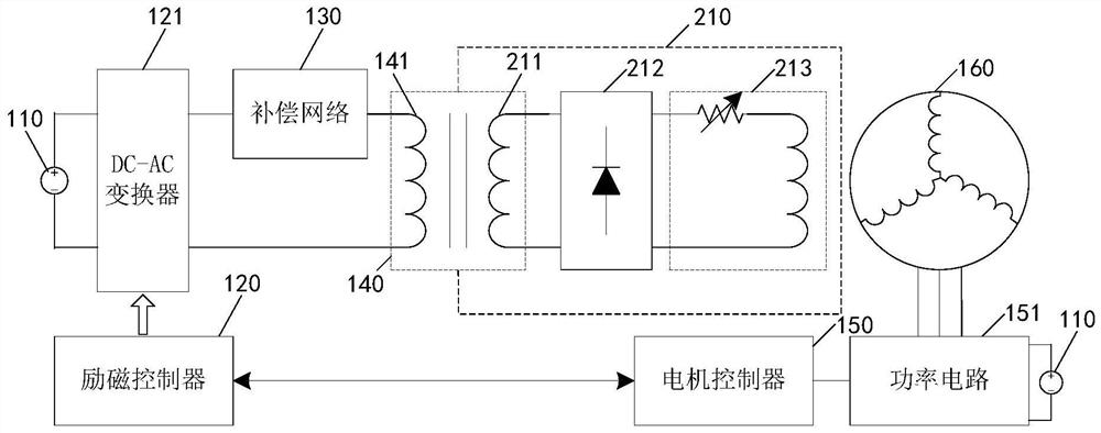
[0066] An embodiment of the present application provides a wireless excitation system, which will be described in detail below with reference to the accompanying drawings.

[0067] see figure 2 , which is a schematic diagram of a radio excitation system provided by an embodiment of the present application.

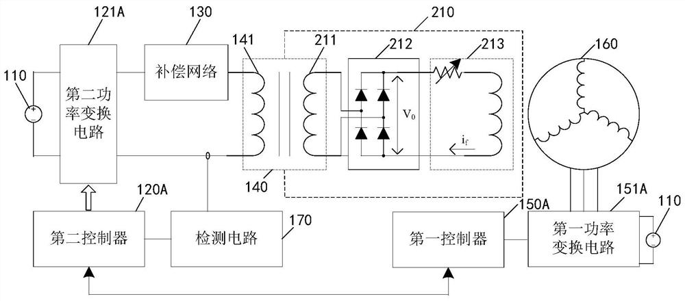
[0068] The wireless excitation system provided in the embodiment of the present application includes: a second controller 120A, an excitation transformer 140, an excitation rectification circuit 212, an electric excitation motor, a second power conversion circuit 121A, a first power conversion circuit 151A, a first controller 150A and detection circuit 170 .

[0069] Wherein, the electric excitation motor includes a motor stator and a motor rotor 210 . The stator of the motor is the stationary part of the motor, mainly including an iron core (not shown in the figure), a stator winding 160 and a frame (not shown in the figure). The motor rotor is a rotating part in the ...

Embodiment 2

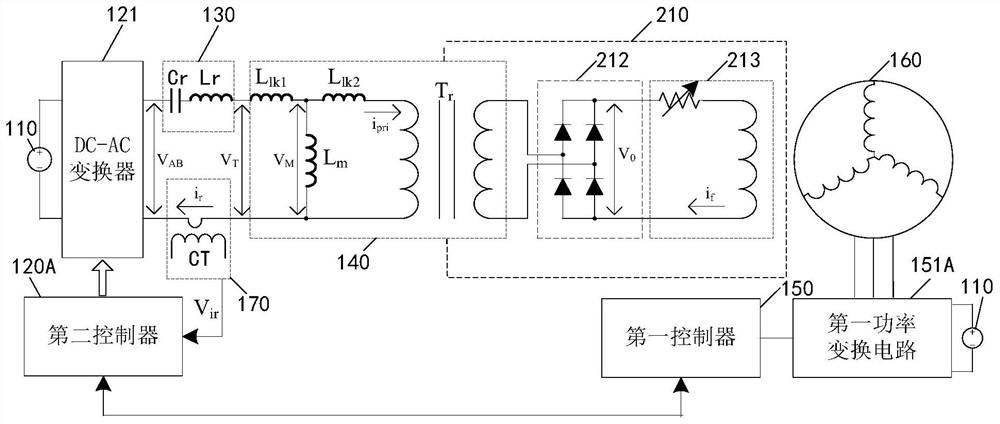
[0081] In order to make those skilled in the art understand the technical solution of the present application more clearly, the detection principle of the wireless excitation system will be described in detail below.

[0082] see image 3 , which is a schematic diagram of another wireless excitation system provided by the embodiment of the present application.

[0083] Wherein, the compensation network 130 includes an inductor Lr and a capacitor Cr. The inductance value of the inductor Lr and the capacitance value of the capacitor Cr are known parameters during system design. The second power conversion circuit 121A is taken as the DC-AC converter 121 as an example for description.

[0084] image 3 The excitation transformer 140 is treated equivalently in the above, and its equivalent model includes: the leakage inductance L of the primary side lk1 , The leakage inductance L of the secondary side lk2 , The exciting inductance is L m and the ideal transformer T r .

[...

Embodiment 3

[0116] In the above embodiments, the principle of the second controller judging whether there is a fault in the wireless excitation system by using the electrical parameters is explained. The principle of the second controller using the received response signal to detect the fault will be specifically described below.

[0117] see Figure 5 , which is a schematic diagram of pulse current excitation and response signals provided in the embodiment of the present application.

[0118] see also image 3 , after the pulse current excitation is injected into the primary side circuit of the excitation transformer through the second control 120A, the pulse current excitation corresponds to the voltage V AB The waveform is as Figure 5 shown.

[0119] The second controller 120A acquires the signal V ir Waveform characteristics, including frequency and amplitude. Signal V ir The frequency and amplitude characterize the current response of the primary side of the excitation transfo...


PUM


Abstract

The invention discloses a radio excitation system, a detection method and an electric vehicle, and relates to the technical field of electronic power. The input end of a first power conversion circuit of the system is connected with a power supply, and the output end is connected with a stator winding of an electro-magnetic motor; the input end of a second power conversion circuit is connected with the power supply and the output end of the second power conversion circuit is connected with a primary side of an excitation transformer; the excitation transformer transmits energy required by an excitation winding of the electro-magnetic motor from the stator to the rotor. A first controller controls the first power conversion circuit to inject current excitation to a stator winding so that the current can be generated on the excitation winding. A detection circuit obtains a response signal of the primary side of the excitation transformer and sends a response signal to a second controller; the second controller controls the second power conversion circuit to inject pulse current excitation to the primary side of the excitation transformer and determines the electrical parameters of the excitation transformer by using the response signal when the secondary side of the excitation transformer is short-circuited and open-circuited by the current generated on the excitation winding. The system can be used for detecting the electrical parameters of the radio excitation system.

Description

technical field [0001] The present application relates to the field of electronic power technology, and in particular to a radio excitation system, a detection method and an electric vehicle. Background technique [0002] When the driving motor of the electric vehicle is a permanent magnet synchronous motor, when the motor runs at a high speed, a high-voltage counter electromotive force will be generated on the stator winding of the motor. If the speed of the motor is further increased at this time, the first controller may be damaged. Because the magnetic field generated by the permanent magnet material of the motor rotor cannot be adjusted, the current of the d-axis on the motor stator side (in line with the magnetic field direction of the motor rotor) can only be adjusted to change the air gap magnetic field, thereby reducing the back electromotive force of the motor stator winding, but when increasing When the d-axis current is high, the efficiency of the motor will be s...

Claims


Application Information

Patent Timeline
Patent Type & Authority Applications(China)
IPC IPC(8): H02P21/14H02P25/022H02P25/18H02P29/024H02P9/14
CPCH02P21/14H02P25/022H02P25/18H02P29/024H02P9/14H02P25/03
Inventor 舒为亮范永滔陈双全
Owner HUAWEI TECH CO LTD
Why Eureka
Try Eureka