
Intelligent dimming device and method of LED (light-emitting diode)

An intelligent dimming, LED light string technology, applied in lighting devices, light sources, electric light sources, etc., can solve the problems of LED stroboscopic or noise, unstable conduction angle, uneven waveform, etc., to improve service life and cost. Low, simple circuit effect

Inactive Publication Date: 2012-12-26
SHANGHAI UNIV
View PDF5 Cites 7 Cited by
  • Summary
  • Abstract
  • Description
  • Claims
  • Application Information

AI Technical Summary

Problems solved by technology

Different thyristors have different maintenance currents, and the greater the power, the greater the maintenance current required. If the maintenance current is not enough, the conduction angle will be unstable, the output waveform will be uneven, and vibrations and spikes will occur. Flickering occurs when such an unstable output is applied to an LED
PWM dimming modulates the control signal of the LED driver chip to the gate of the MOS transistor by changing the duty cycle of the input pulse signal to achieve dimming. The advantages are simple application, high efficiency, high precision, and good dimming effect. The disadvantage is that when When the PWM dimming frequency is too small or too high, there will be LED strobe or noise, etc.

Method used


Image

  • Intelligent dimming device and method of LED (light-emitting diode)
  • Intelligent dimming device and method of LED (light-emitting diode)
  • Intelligent dimming device and method of LED (light-emitting diode)

Examples


Embodiment 1

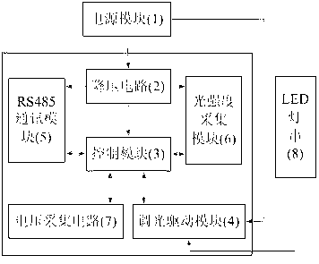
[0026] see figure 1 : This LED intelligent dimming device includes a power module (1), a step-down circuit (2), a control module (3), a dimming drive module (4), a communication module (5), a light intensity acquisition module (6), a voltage Acquisition circuit (7) and LED light string (8). The power supply module (1) is connected to the step-down circuit (2) and the dimming drive module (4) in one direction; the output end of the step-down circuit (2) is connected to the control module (3) and the RS485 communication module (5) respectively. ), the light intensity acquisition module (6) is connected to the power input end; the positive end of the LED light string (8) is connected to the power module (1), and the negative end is connected to the dimming drive module (4); the voltage acquisition circuit (7 ) to connect the dimming driver module (4).

[0027] In this embodiment, a 12V DC power supply is used to power the system.

Embodiment 2

[0029] This embodiment is basically the same as Embodiment 1, and the special features are as follows:

[0030] See attached image 3 , The step-down circuit (2) adopts the step-down chip LM2575 to reduce the power supply voltage to a stable 3.3V, and supplies power for the control module, communication module, and light intensity acquisition module.

[0031] See attached Figure 4 , the control module (3) uses NuMicro M051 series chips as the main controller. NuMicro M051 series is a 32-bit microcontroller with ARM Cortex-M0 as the core. It has rich communication interfaces and the cost is only equivalent to the traditional 8-bit microcontroller. It integrates UART, I2C, PWM, ADC and other functional modules, which can reduce the number of peripheral components and save space and cost. The NuMicro M051 series includes M052, M054, M058 and M0516. This embodiment selects M0516LAN.

[0032] See attached Figure 5 , Dimming driver module (4) Select the LED constant current d...

Embodiment 3

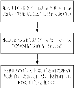
[0037] See attached figure 2 , this LED intelligent dimming method is applied to the above-mentioned device for dimming, and the specific operation steps are as follows:

[0038] Step B1: switch between automatic dimming and manual dimming according to user instructions.

[0039] Step B2: Adjust the duty cycle of the PWM signal according to the illuminance value or the user dimming signal. Among them, the frequency of the PWM signal is set to 200HZ. At this time, there is no flicker and no noise, and the duty cycle of the PWM signal can be adjusted arbitrarily between 0% and 100%.

[0040]Step B3: Control the switch drive signal of the dimming drive module according to the PWM signal, and control and adjust the brightness of the LED light string. The current on the LED light string is mainly determined by the reference voltage of the driver chip and the sampling resistor Rcs. The high and low levels of the PWM signal can control the working state of the LED driver. When the...


PUM


Abstract

The invention relates to an intelligent dimming device and method of an LED (light-emitting diode). The device comprises a power module, a reduction voltage circuit, a control module, a dimming drive module, a communication module, a light strength collecting module, a voltage collecting circuit and an LED lamp string; the power module is respectively in one-way connection with the reduction voltage circuit and the dimming drive module; the output end of the reduction voltage circuit is respectively connected with power inlet ends of the control module, the communication module and the light strength collecting module; the anode end of the LED lamp string is connected with the power module; the cathode end is connected with the dimming drive module, and the voltage collecting circuit is connected with the dimming drive module. The intelligent dimming device has the advantages that two dimming modes of automatic dimming and manual dimming can be achieved; the advantage of energy conservation of the LED is played to a greater extent; the dimming drive module utilizes a constant-current driver; the LED driver is in a work state all the time in a dimming process; the impact current born by the LED lamp string is small; improvement of the service life of the LED is facilitated, and the applicability is strong.

Description

technical field [0001] The invention belongs to the field of LED lighting control, and relates to an LED intelligent dimming device and method, in particular to LED dimming realized by means of PWM. Background technique [0002] In recent years, LEDs have been widely used as a new generation of green and efficient lighting sources. LEDs have high luminous efficiency, low energy consumption, long life, recyclable materials, no pollution to the environment, and good dimming performance. In order to create a more comfortable lighting atmosphere and save energy, the research on LED dimming technology is extremely important. [0003] At present, there are three main ways of LED dimming on the market: one is linear dimming, the other is thyristor dimming, and the third is PWM dimming. Linear dimming is mainly based on the principle of simple voltage division. Its advantages are simple application and no interference. The disadvantages are inflexibility, low efficiency, and incons...

Claims


Application Information

Patent Timeline
Patent Type & Authority Applications(China)
IPC IPC(8): H05B37/02
Inventor 尹纪庭余建波王小乐
Owner SHANGHAI UNIV
Learn More