Minimally invasive expansion tool used for spinal canal expansion

A technology for dilating tools and spinal canals, applied in medical science, surgery, etc., to achieve the effect of reducing tightness and resistance

Active Publication Date: 2013-01-02
BONE MEDICAL TECH OF SUZHOU CO LTD
View PDF4 Cites 0 Cited by
  • Summary
  • Abstract
  • Description
  • Claims
  • Application Information

AI Technical Summary

Problems solved by technology

For spinal stenosis and dilation, minimally invasive still faces many difficulties
So far, there is no surgical method and corresponding special surgical tool that can realize the minimally invasive surgery of spinal canal dilatation.

Method used


Image

  • Minimally invasive expansion tool used for spinal canal expansion
  • Minimally invasive expansion tool used for spinal canal expansion
  • Minimally invasive expansion tool used for spinal canal expansion

Examples


Embodiment 1

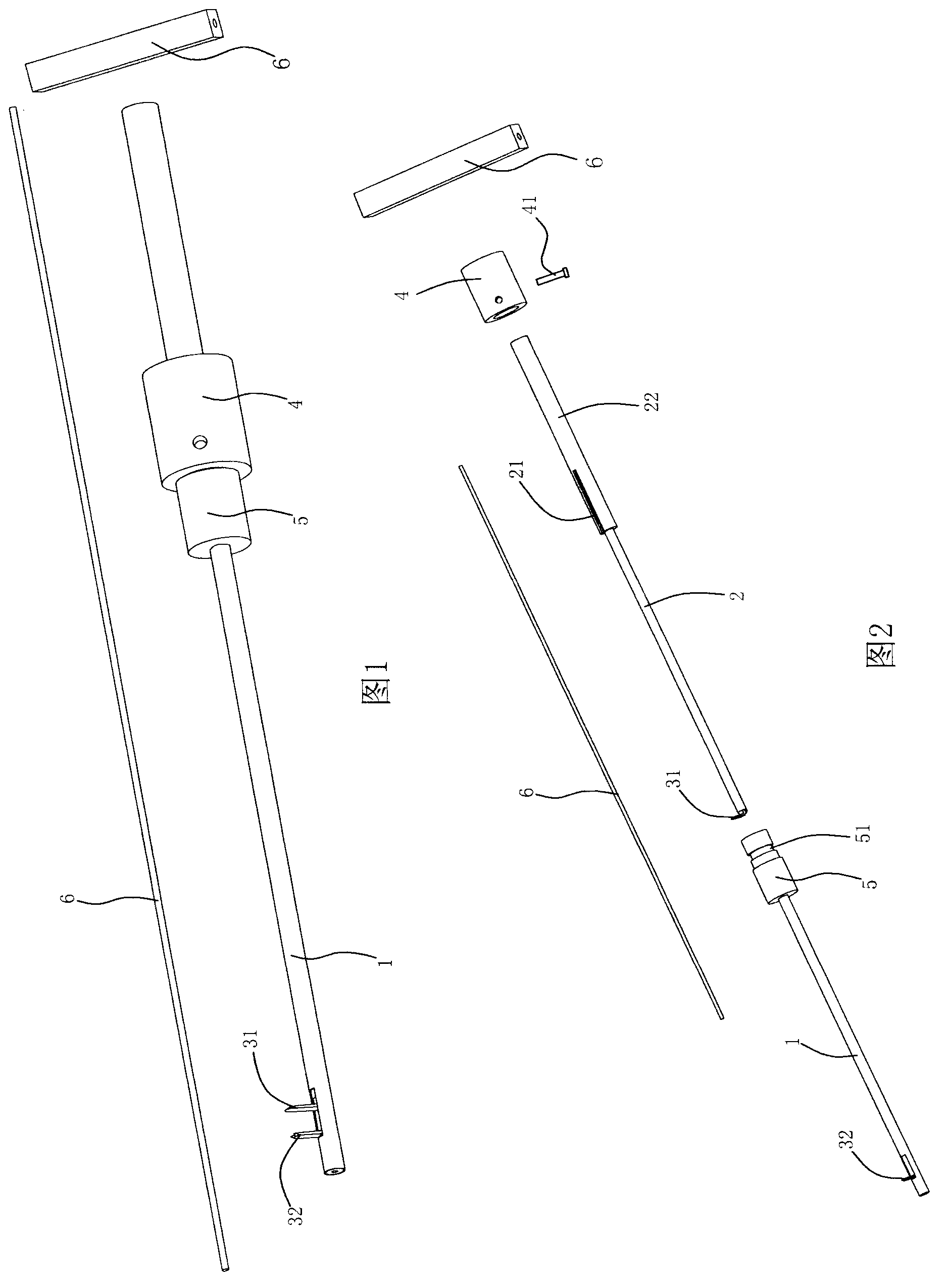
[0031] Embodiment one: if figure 1 , figure 2 As shown, a minimally invasive expansion tool for spinal canal expansion includes a sleeve rod 1, an expansion rod 2 slidingly sleeved with the sleeve rod, and an expansion mechanism located in the sleeve rod 1, and the expansion mechanism includes a first expansion part 31 and a second expansion part 32, the first expansion part is hinged with the expansion rod 2, the second expansion part is hinged with the sleeve rod 1, and the side wall of the sleeve rod 1 is provided for the The first expansion part 31 and the second expansion part 32 radially protrude, move, and retract the opening 11. The expansion rod 2 has a through hole 23 along the axis, and the first expansion part 31 has a first expansion hole. 311 , the second expansion member 32 has a second expansion hole 321 , and also includes an expansion guide rod 6 that penetrates or exits the through hole 23 , the first expansion hole 311 , and the second expansion hole 321 ...

Embodiment 2

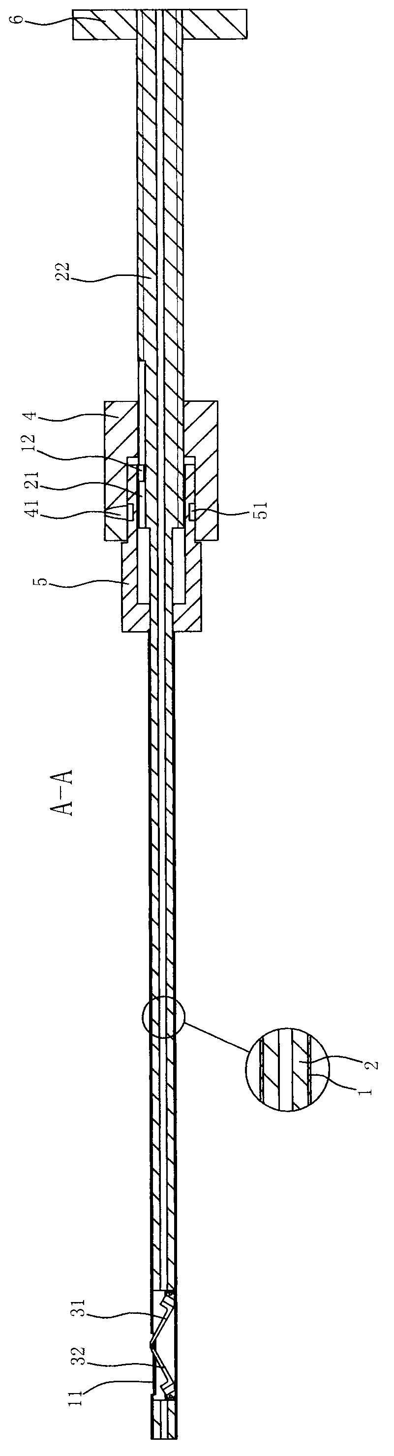
[0033] Embodiment 2: On the basis of the foregoing embodiments, as figure 2 , Figure 4 As shown, the expansion rod 2 is provided with a guide groove 21 along the axial direction, and the position of the guide groove 21 corresponds to the position where the first expansion member and the second expansion member protrude, move, and retract. The rod 1 is provided with a protrusion 12 , the position of the protrusion 12 corresponds to the position of the opening 11 and is located in the guide groove 21 . When the sleeve rod 1 and the expansion rod 2 slide relative to each other, they will slide along the direction of the guide groove 21, and there will be no circumferential position change. At the same time, the position of the guide groove 21 corresponds to the positions where the expansion mechanism 3 extends, moves, and retracts, that is, it is in a straight line corresponding to the positions where the first expansion member 31 and the second expansion member 32 extend, mov...

Embodiment 3

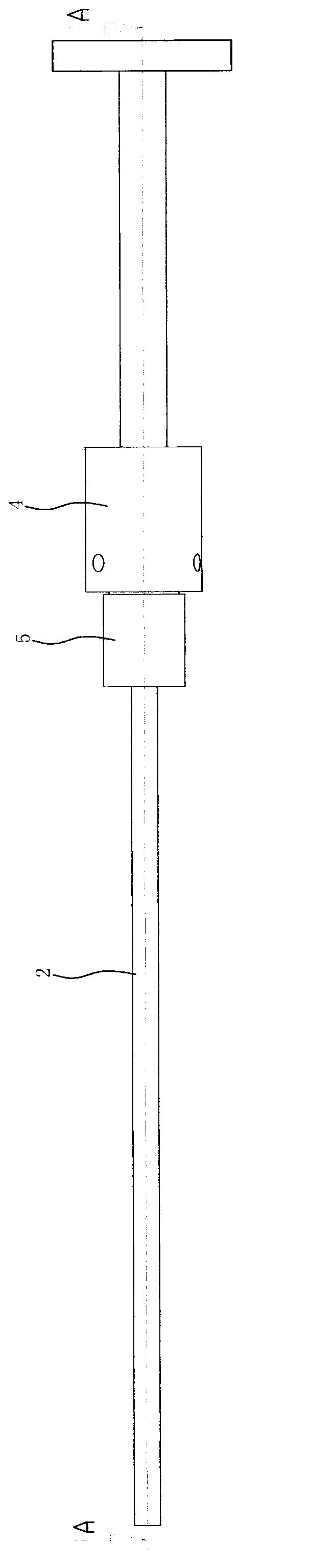
[0034] Embodiment three: on the basis of the foregoing embodiments, as Figure 1 to Figure 4 As shown, it also includes a driving part that drives the sleeve rod 1 and the expansion rod 2 to slide relatively. The drive part includes a drive screw sleeve 4 and a fixed sleeve 5. , or one-piece molding. The rear section of the expansion rod 2 is set as a threaded rod 22 and is threadedly connected with the driving screw sleeve 4 , and the fixed sleeve 5 is engaged with the driving screw sleeve 4 in a circumferential direction. The portion where the fixing sleeve 5 protrudes into the driving screw sleeve 4 is provided with a groove 51 along the circumferential direction, and the driving screw sleeve 4 is provided with a driving member 41 , and the driving member 41 extends into the groove 51 . The guide groove 21 is located at the front of the threaded rod 22 , and the protrusion 12 is disposed on the fixing sleeve 5 .

[0035] When the screw sleeve 4 is driven to rotate, the en...


PUM


Abstract

The invention provides a minimally invasive expansion tool for spinal canal expansion. The minimally invasive expansion tool adopts a loop bar and an expansion rod which are mutually sheathed. The expansion rod and the loop rod are respectively hinged with an expansion piece, the expansion pieces are driven to move through the opposite sliding of the loop rod and the expansion rod, and the expansion pieces radially rotate at contact parts, extend out from an opening of the loop rod, and extend into a gap at a cutting part to be expanded. The expansion tool provided by the invention is applied in the novel minimally invasive spinal canal stenosis dilatation, and is used for cutting, prolonging and refixing the vertebral pedicle bone. Moreover, the minimally invasive expansion tool is only operated in a drill hole which is about 3mm in diameter. The minimally invasive expansion tool is used for expanding and stretching soft tissues, such as ligaments, muscles and the like around the vertebral pedicle bone so as to loosen and reduce the packing force of the soft tissue to the vertebral pedicle bone and reduce the packing resistance of the soft tissues as much as possible at the time of fixing screws, so that wounds of patients become small, and further, the minimally invasive operation is realized. The minimally invasive expansion tool has advantages that the minimally invasive expansion tool can greatly shorten the convalescence of patients, and lower the operation cost.

Description

technical field [0001] The invention relates to a surgical medical instrument, in particular to a minimally invasive expansion tool for spinal canal expansion in spinal surgery. Background technique [0002] Spinal stenosis is one of the common diseases in middle-aged and elderly patients. Spinal stenosis is caused by bone hyperplasia in the lumbar spine itself, which causes the spinal canal to become smaller and squeezes the nerves passing through it, causing pain, inability to bend the waist, and numbness of hands and feet. , walking with a limp, etc. Spinal stenosis dilation is one of the main operations in spinal surgery. Performing spinal canal dilation requires the use of specialized surgical tools. [0003] At present, spinal stenosis dilation is an open operation. It needs to make an incision with a length of more than 10 cm on the patient's back, and then cut off and re-fix the vertebrae. This kind of open surgery has a large trauma area and damages soft tissues,...

Claims


Application Information

Patent Timeline
Patent Type & Authority Applications(China)
IPC IPC(8): A61B17/02A61B17/56
Inventor 罗宗平杨惠林
Owner BONE MEDICAL TECH OF SUZHOU CO LTD
Why Eureka
Try Eureka