Flow control valve

A flow regulating valve, the technology of the first flow passage, applied in the valve details, valve device, sliding valve and other directions, can solve the problems of rotation influence, affecting the rotational stability and reliability of the drive shaft 78, and achieve the effect of avoiding the influence

Active Publication Date: 2013-01-02
ZHEJIANG SANHUA COMMERCIAL REFRIGERATION CO LTD
View PDF11 Cites 5 Cited by
  • Summary
  • Abstract
  • Description
  • Claims
  • Application Information

AI Technical Summary

Problems solved by technology

Since the fluid enters the gap between the drive shaft 78 and the discharge piston 130, the fluid will affect the rotation of the drive shaft 78 in the discharge piston 130, which will affect the stability and reliability of the drive shaft 78 rotation.

Method used


Image

  • Flow control valve
  • Flow control valve
  • Flow control valve

Examples


Embodiment Construction

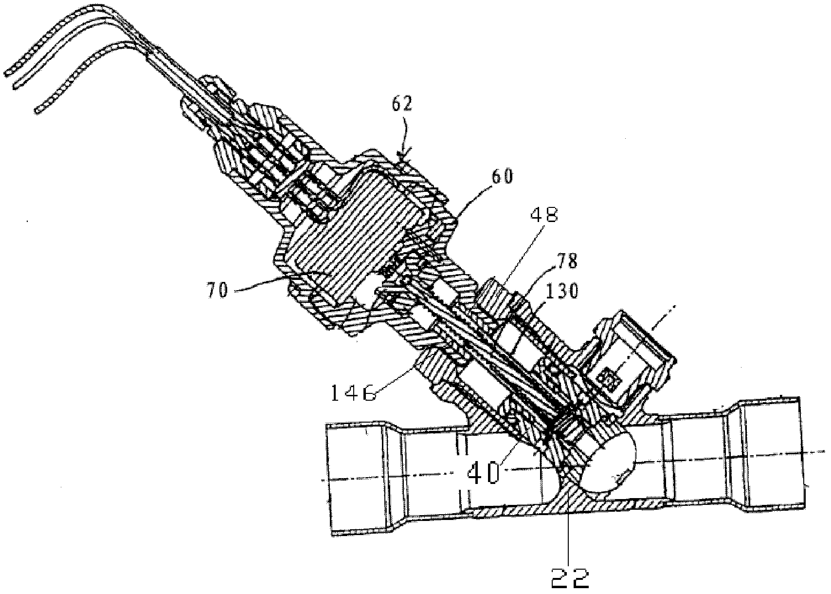
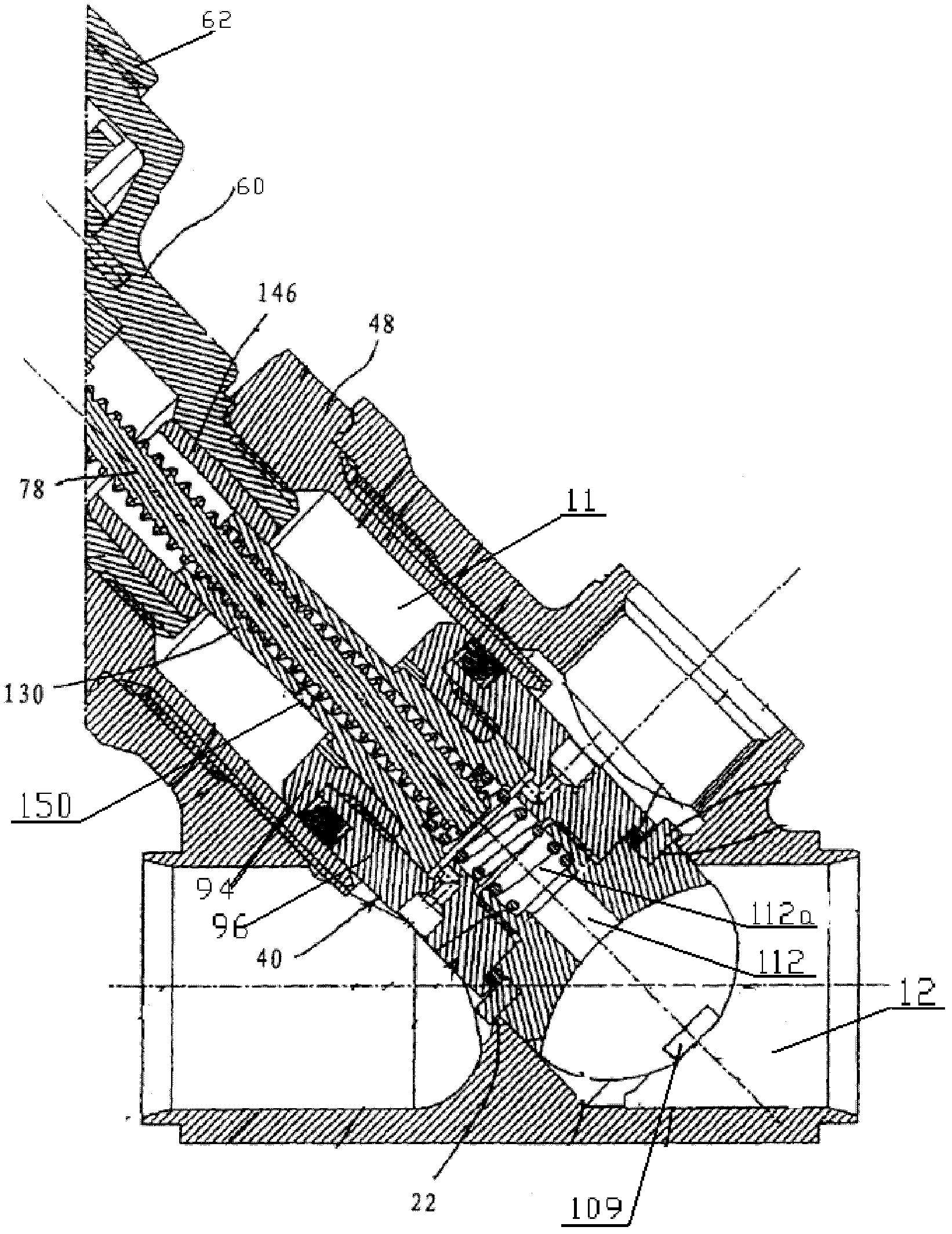
[0049] The core of the present invention is to provide a flow regulating valve. The design of the balance channel of the flow regulating valve can timely and effectively balance the fluid pressure on the valve stem, and on the other hand, avoid affecting the rotation of the screw rod.

[0050] In order to enable those skilled in the art to better understand the technical solutions of the present invention, the present invention will be further described in detail below in conjunction with the accompanying drawings and specific embodiments.

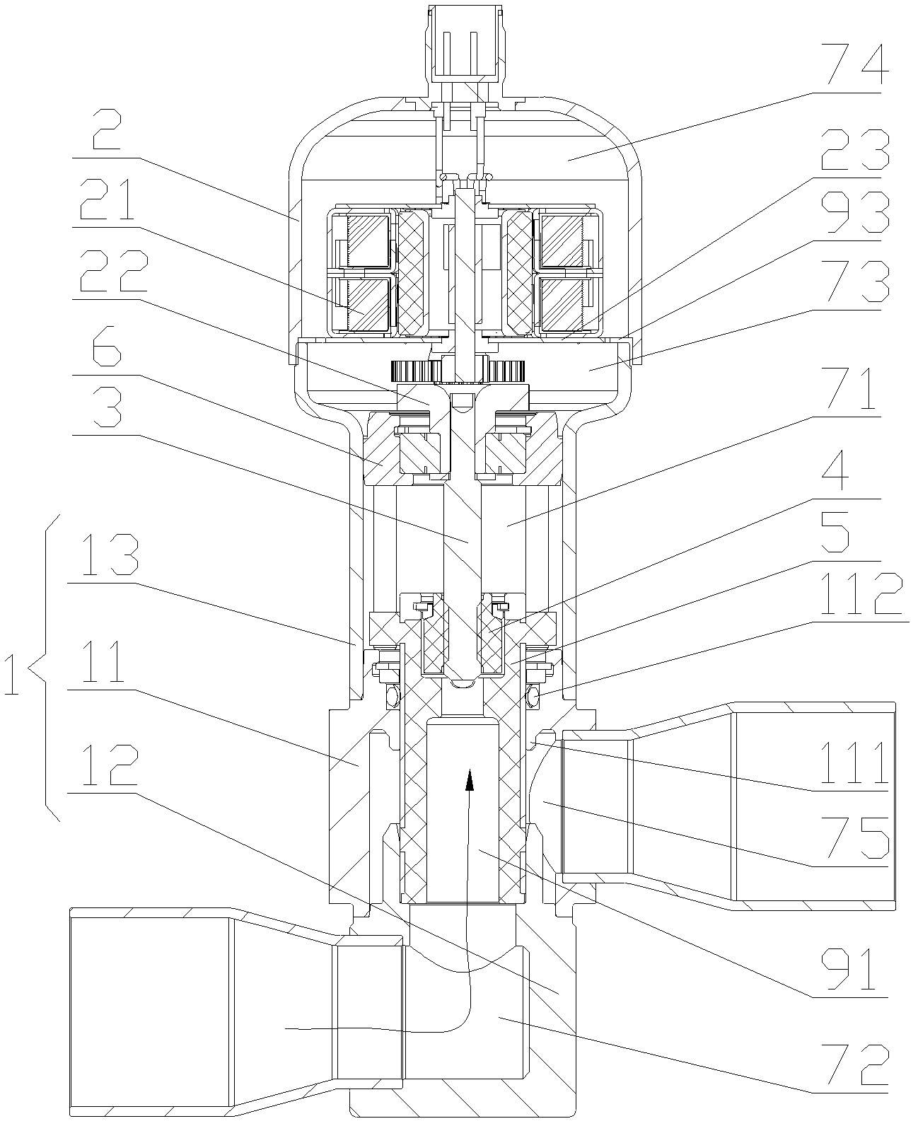
[0051] Please refer to image 3 , image 3 It is a structural schematic diagram of a flow regulating valve in an embodiment of the present invention.

[0052] In the basic technical solution of the present invention, the flow regulating valve includes a valve seat 1 and a housing 2 connected to the valve seat 1. A motor 21 is provided in the housing 2. The output shaft of the motor 21 passes through the The gear system 22 is in transmiss...


PUM


Abstract

The invention discloses a flow control valve. The flow control valve comprises a valve seat (1) and a shell (2), wherein a motor (21) is arranged inside the shell (2) and is connected with a screw rod (3); the screw rod (3) is connected with a nut (4); the nut (4) is connected with a valve rod (5); balance fluid channels which communicate first cavities (71) with a second cavity (72) are arranged on the valve rod (5); an installation groove (51) is arranged inside the valve rod (5); the whole nut (4) or the lower part of the nut (4) is matched in the installation groove (51); and the balance fluid channels comprise first fluid channels which are formed between the nut (4) and the inner walls of the installation groove (51). The flow control valve has the following beneficial effects that through design of the balance fluid channels, on one hand, the fluid pressure borne by the valve rod (5) can be timely and effectively balanced, and on the other hand, impacts on rotation of the screw rod (3) can be avoided.

Description

technical field [0001] The invention relates to the technical field of fluid control components, in particular to a flow regulating valve. Background technique [0002] The flow regulating valve is an important part of the refrigeration system, and it is another basic part of the four basic components of the refrigeration system except the evaporator, compressor and condenser. The working process of the flow regulating valve is generally: as the coil device is energized or de-energized, the valve needle adjusts the opening of the valve port, thereby adjusting the flow of the refrigerant. In addition, flow control valves are also widely used in other fluid control fields such as hydraulic systems and oil transportation. [0003] In the prior art, Chinese patent No. 200580023202.7 discloses a flow regulating valve; specifically, please refer to figure 1 and figure 2 , figure 1 It is a structural schematic diagram of a flow regulating valve in the prior art, figure 2 for...

Claims


Application Information

Patent Timeline
Patent Type & Authority Applications(China)
IPC IPC(8): F16K3/30F16K31/50F16K31/53
Inventor 不公告发明人
Owner ZHEJIANG SANHUA COMMERCIAL REFRIGERATION CO LTD
Why Eureka
Try Eureka