Electric hydraulic executing device

An actuator and hydraulic technology, applied in the direction of valve device, valve operation/release device, engine components, etc., can solve the problems of low control accuracy, cumbersome maintenance work, large device volume, etc., and achieve adjustable valve closing speed, The design is reliable and the effect of reducing work loss

Active Publication Date: 2014-06-11
SHANDONG JIAXIN AUTOMATION
View PDF3 Cites 0 Cited by
  • Summary
  • Abstract
  • Description
  • Claims
  • Application Information

AI Technical Summary

Problems solved by technology

However, this kind of control valve device has large volume, high failure rate, low control accuracy and cumbersome maintenance work.

Method used


Image

  • Electric hydraulic executing device
  • Electric hydraulic executing device

Examples


Embodiment Construction

[0023] In order to clearly illustrate the technical features of this solution, the present invention will be described in detail below through specific implementation modes and in conjunction with the accompanying drawings.

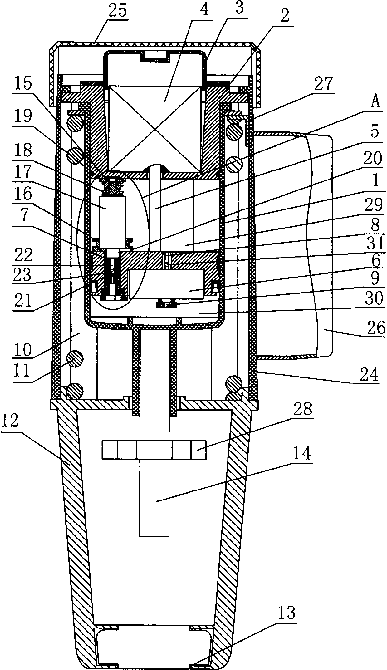
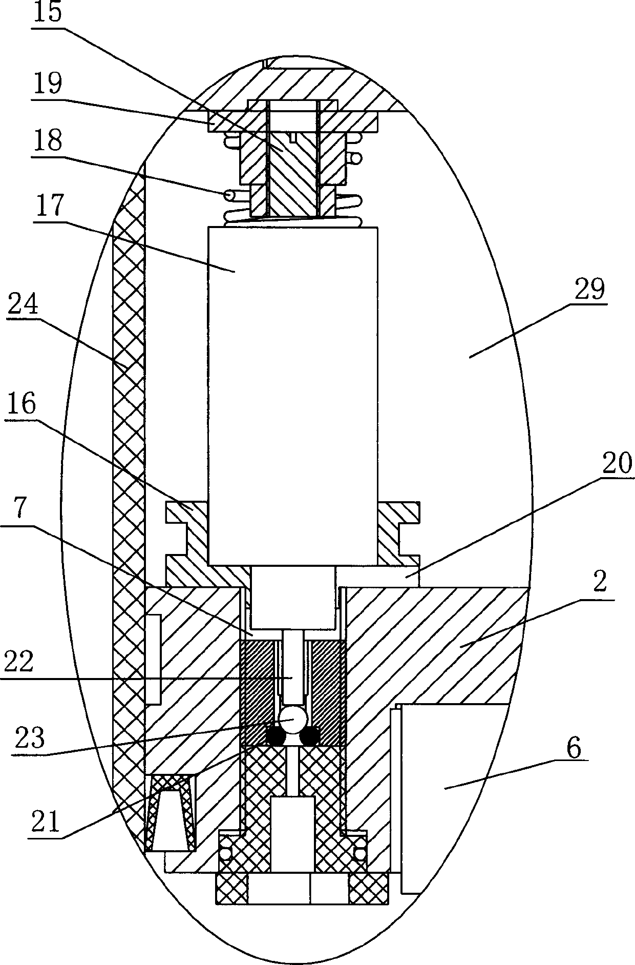
[0024] Such as Figure 1-2 Shown, the present invention comprises support 12, is provided with buckle 13 at support 12 lower ends, is provided with several pull rods 10 evenly along the circumference at support 12 top edge, and the top of pull rod 10 is connected with a piston 2 tops, on the piston 2 A cylinder body 1 is sleeved on the outer side, and the upper end of the return spring 11 sleeved on the outside of the cylinder body 1 is in conflict with the top end of the cylinder body 1 , and the lower end is in conflict with the top end of the support 12 . The piston 2 cooperates with the cylinder body 1 outside the piston 2 to form a normal pressure oil chamber 29 and a high pressure oil chamber 30 which are sealed and isolated from each other under th...


PUM


Abstract

The invention provides an electric hydraulic executing device, comprising a bracket with a buckle at the lower end. The top end of a pull rod arranged at the top end of the bracket is fiedly connected with a piston; a cylinder body is sleeved at the outer side of the piston; the upper end of a resetting spring sleeved at the outer side of the cylinder body is abutted against the cylinder body, and the lower end of the resetting spring is abutted against the bracket; the piston and the cylinder body are matched below the middle part and the bottom part of the piston, so as to form a constant-pressure oil cavity and a high-pressure oil cavity, which are isolated in a sealed manner; an output shaft of a motor arranged in a cavity between a sealing cover which is fixedly connected at the top end of the piston and the top of the piston passes through the lower parts of the constant-pressure oil cavity and the lower part of the piston, and is connected with a gear pump which is internally embedded at the bottom of the piston; an oil inlet of the gear pump is communicated with the constant-pressure oil cavity through an oil inlet channel, and an oil outlet of the gear pump is communicated with the high-pressure oil cavity; the piston between the constant-pressure oil cavity and the high-pressure oil cavity is provided with an oil return channel provided with an oil return control mechanism; a driving rod provided with a mutual control plate is arranged at the bottom of the cylinder body; and the motor, the gear pump and the oil return control mechanism are respectively connected with a control device. The electric hydraulic executing device has the advantages of small size, reliable property and high control precision.

Description

Technical field: [0001] The invention relates to a hydraulically driven valve device, in particular to an electrohydraulic actuator. Background technique: [0002] In the pipeline adjustment, based on the control requirements of temperature, pressure, pressure difference, flow, etc., it is necessary to adjust the fluid in the pipeline and perform valve position feedback. This is the hardware for various control devices to achieve control purposes on the pipeline site Realize the unit. Precisely controlling the opening position of the heating valve is the key to effectively guarantee the quality of heating. [0003] Among the regulating valves widely used in various industries, straight stroke valves are generally used. At present, most of the valves use a servo motor to control the opening or closing of the valve through a gear reduction device, or a pneumatic method, so as to adjust the size of the fluid. However, this kind of device for controlling the valve has large v...

Claims


Application Information

Patent Timeline
Patent Type & Authority Patents(China)
IPC IPC(8): F16K31/122F16K31/04
Inventor 李建博姜华常晓晨
Owner SHANDONG JIAXIN AUTOMATION
Why Eureka
Try Eureka