Thermoplastic plastic composite tube

A thermoplastic, composite pipe technology, applied in rigid pipes, hoses, pipes, etc., can solve the problems of insufficient joint connection firmness, long clamp connector structure, low joint pressure, etc. Faster collection speed, favorable for electrostatic charge, and low transport resistance

Active Publication Date: 2013-01-02
PETRO OIL & LUBRICANT RES INST OF THE GENERAL LOGISITIC DEPT OF PLA +1
View PDF9 Cites 19 Cited by
  • Summary
  • Abstract
  • Description
  • Claims
  • Application Information

AI Technical Summary

Problems solved by technology

[0007] At present, the common methods used for thermoplastic pipe connection include the following three: (1) Fusion, such as hot-melt connection, electric fusion connection or electrofusion-hot-melt connection, using a fusion joint between two thermoplastic pipes, this connection The joint formed by this method bears low pressure; (2) buckle connection, insert the socket end of a metal pipe fitting into the reinforced thermoplastic pipe, coat a metal sleeve on the reinforced thermoplastic pipe, and mechanically connect the metal sleeve-reinforced thermoplastic pipe The end-pipe fitting socket end is compressed into a joint. This connection method often results in a smaller inner diameter of the joint than other parts of the thermoplastic pipe, which leads to an increase in the resistance of the transported liquid. At the same time, how to ensure sealing and withstand high axial and The radial loads are also different; (3) The clamps are directly socketed, and there are card slots outside the joints of the two joints, and the clamps are directly sleeved in the card slots for connection. The disadvantage is that the structure of the clamp connector is long. , heavy weight, many connecting bolts, and cannot be mechanized laying, etc., it is more suitable for low-pressure pipelines
[0008] In addition, for the above connection methods, there are still problems such as the joint connection is not strong enough, the installation speed is not fast, etc.

Method used


Image

  • Thermoplastic plastic composite tube

Examples


Embodiment Construction

[0047] The present invention will be described in detail below through exemplary specific embodiments in conjunction with the accompanying drawings. The features and advantages of the present invention will become clearer and more specific with these descriptions.

[0048] The same reference numbers in the figures indicate functionally identical or similar elements.

[0049]The word "exemplary" is used exclusively herein to mean "serving as an example, embodiment, or illustration." Any embodiment described herein as "exemplary" is not necessarily to be construed as superior or better than other embodiments. While various aspects of the embodiments are shown in drawings, the drawings are not necessarily drawn to scale unless specifically indicated.

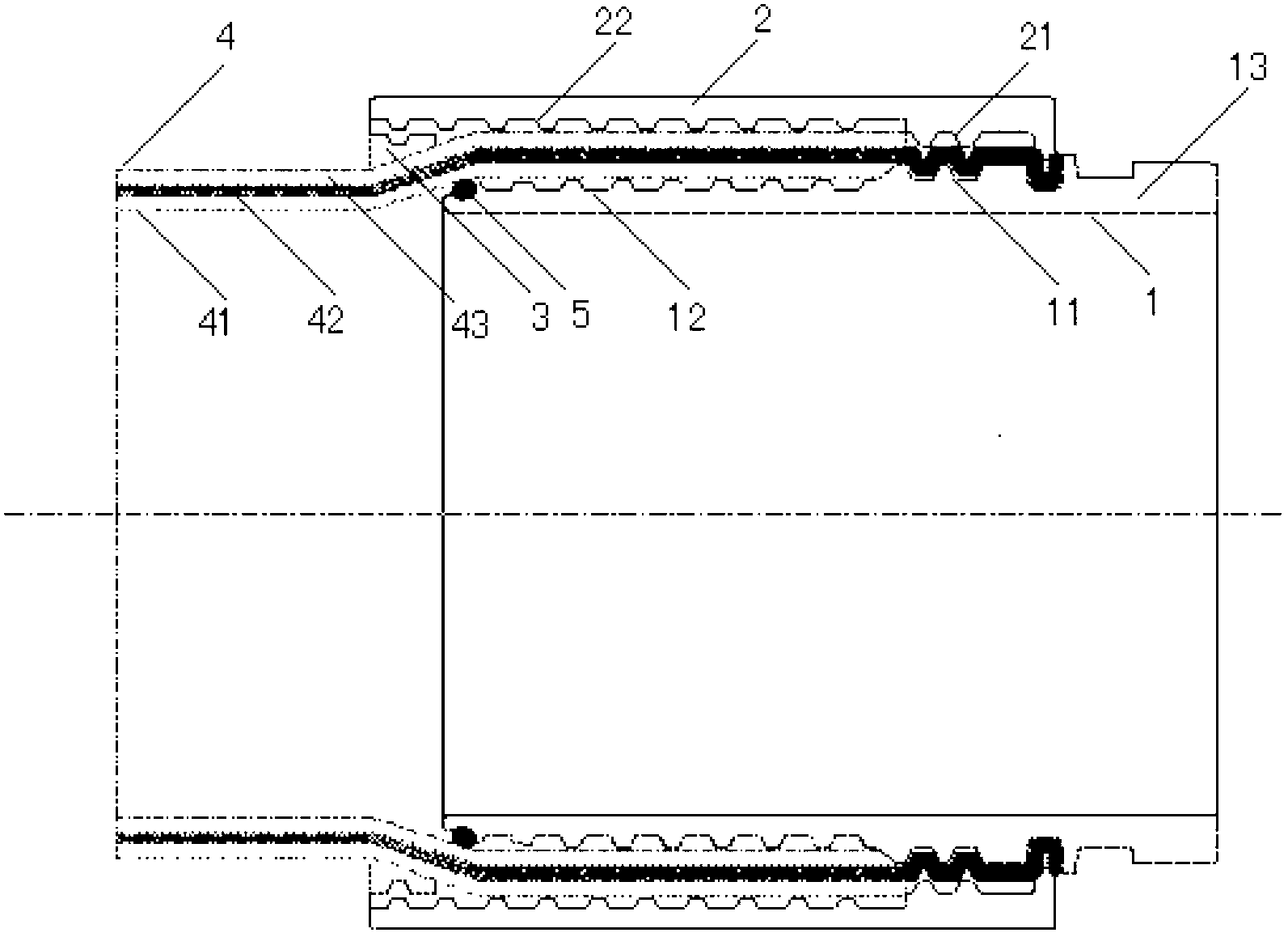
[0050] According to the present invention, a thermoplastic composite pipe is provided, which comprises a thermoplastic composite pipe body. At the end of the thermoplastic composite pipe body, a core pipe is crimped inside and a ...


PUM


Abstract

The invention relates to a thermoplastic plastic composite tube, which comprises a thermoplastic plastic composite tube body and a joint. The joint comprises a core tube and a jacket, which are buckled on both ends of the tube body; the end of a tube body of the thermoplastic plastic composite tube is expanded in a radial direction, so that the inner diameter of the core tube is equal to the inner diameter of the tube body, an inner layer and an outer layer of the tail end of the end of the tube body are stripped, the expanded end of the tube body is buckled between a trapezoidal tooth groove outside the core tube and a trapezoidal tooth groove of the jacket; and the end of the core tube is a joint connecting part. The thermoplastic plastic composite tube has the advantages of firm joint buckling, good sealing property, high pressure resistance and drawing resistance, the inner diameter of the joint is equal to the inner diameter of the pipeline, and the fluid conveying resistance is reduced.

Description

technical field [0001] The present invention relates to reinforced thermoplastic pipes, and more particularly to thermoplastic composite pipes that can be quickly disassembled. Background technique [0002] Thermoplastic composite pipes have been gradually used in foreign oil and gas fields since the 1990s, and have been tried in domestic oil and gas fields since the beginning of this century. They are mainly used for oil and gas gathering and transportation, water injection and alcohol injection. Now, the application fields of thermoplastic composite pipes include marine flexible pipes, hot spring pipes; petroleum, refined oil, and natural gas transportation; municipal water supply and drainage, oily sewage, seawater desalination; mine water supply, air supply, drainage, coal washing water, and coal powder transportation; Corrosive liquid transportation in chemical plants and steel mills. [0003] Composite pipes generally include a three-layer structure: the inner lining ...

Claims


Application Information

Patent Timeline
Patent Type & Authority Applications(China)
IPC IPC(8): F16L9/147F16L11/08F16L47/08
Inventor 李万利袁长友宋花平刘进立严为群钱晓宇
Owner PETRO OIL & LUBRICANT RES INST OF THE GENERAL LOGISITIC DEPT OF PLA
Why Eureka
Try Eureka