
Photography motion control device

A technology for motion control devices and control devices, applied in the direction of optics, instruments, camera bodies, etc., can solve the problems of inconvenient maintenance, inconvenient operation, complex structure, etc., and achieve the effect of convenient maintenance, convenient operation, and simple structure

Inactive Publication Date: 2013-01-02
郑鹏 +2
View PDF6 Cites 17 Cited by
  • Summary
  • Abstract
  • Description
  • Claims
  • Application Information

AI Technical Summary

Problems solved by technology

However, the existing devices for driving the camera movement are all one-dimensional motion systems, which can only realize straight-line reciprocating motion, and its structure is complex, inconvenient to operate, and inconvenient to maintain.

Method used


Image

  • Photography motion control device
  • Photography motion control device
  • Photography motion control device

Examples


Embodiment Construction

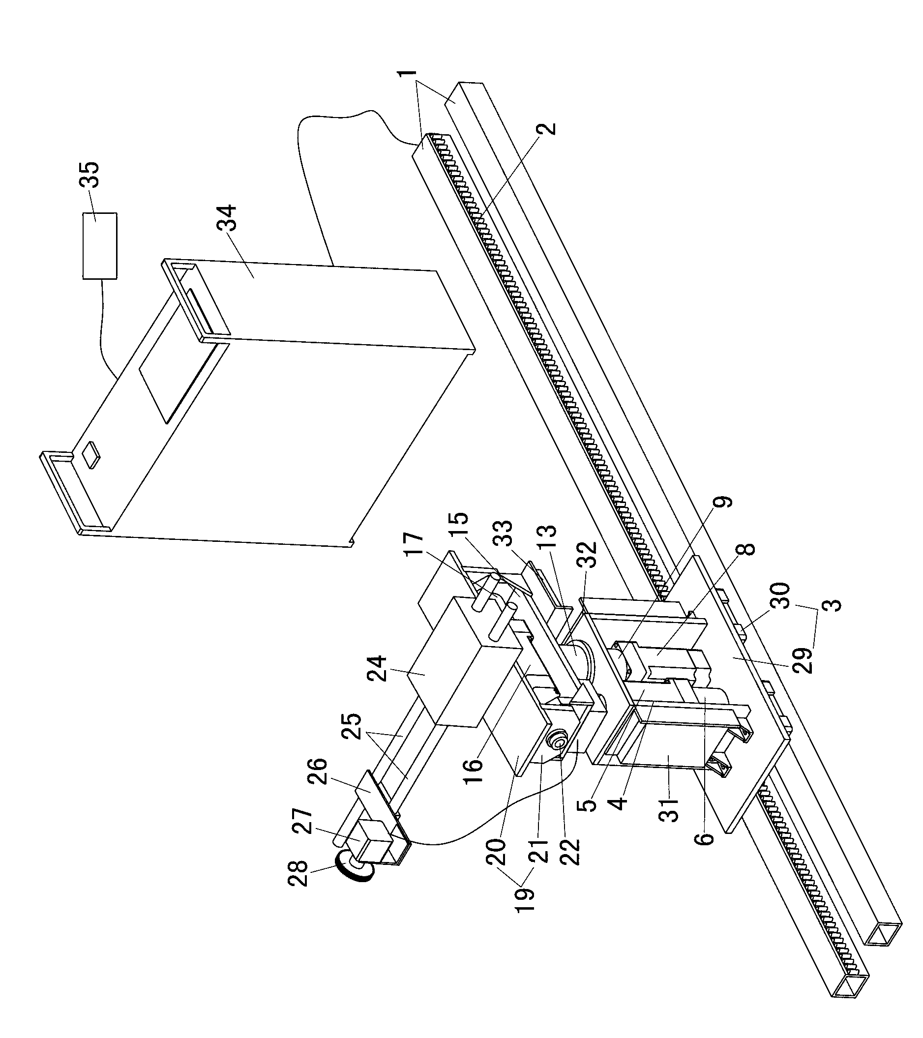
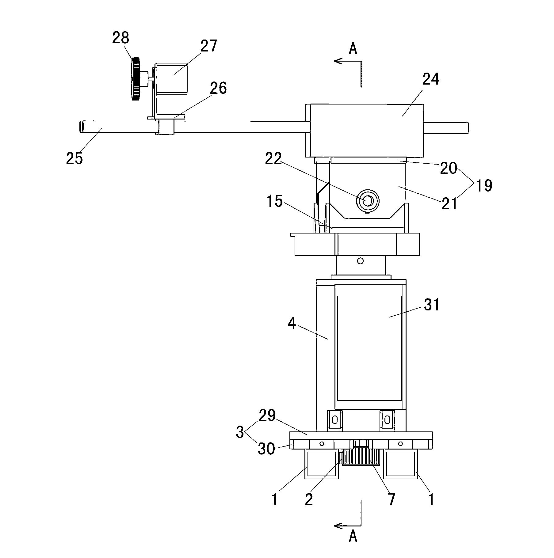
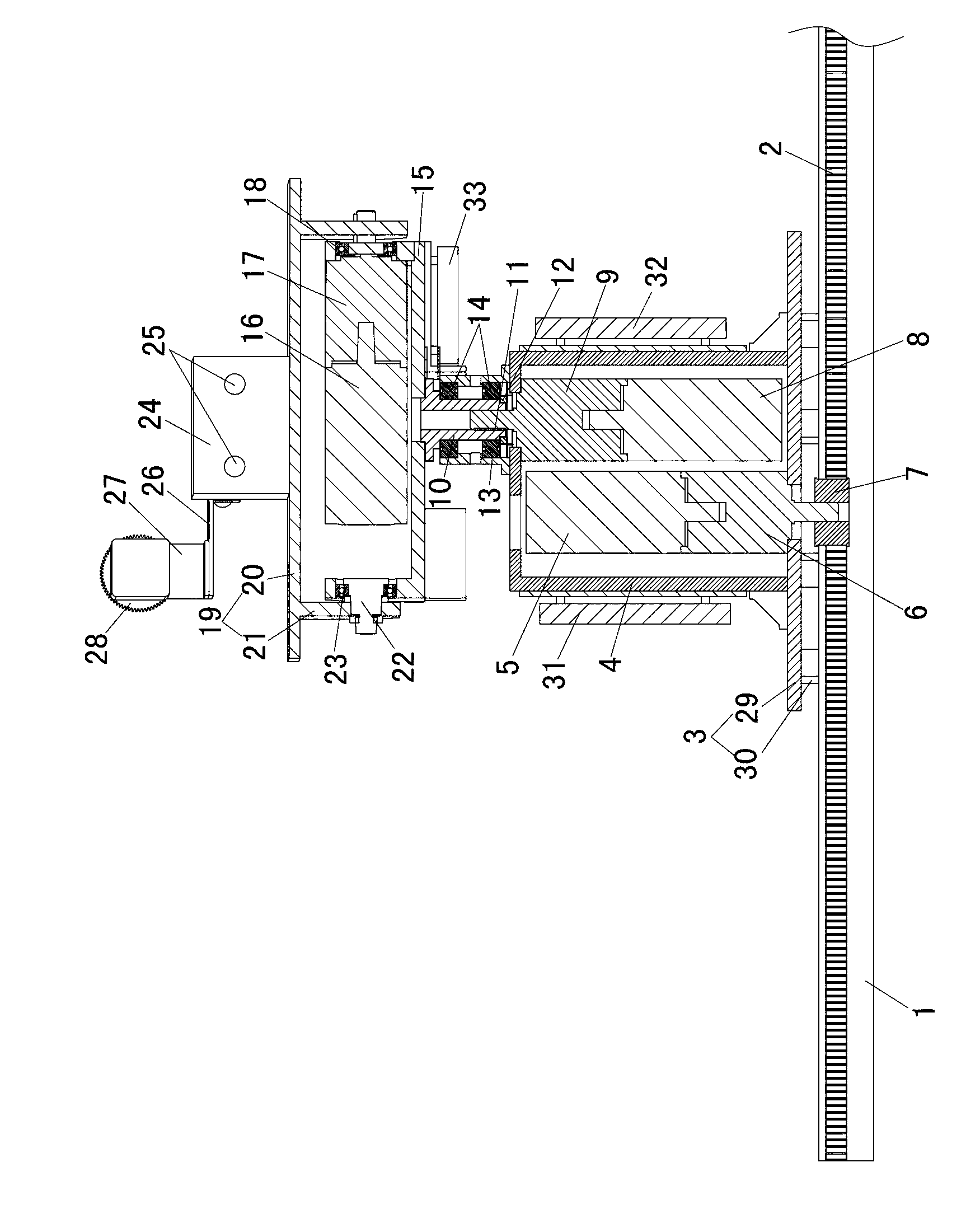
[0025] Such as figure 1 , figure 2 and image 3 As shown, the photographic motion control device of the present invention includes two rails 1 placed horizontally and parallel to each other. The inner surface of one of the tracks 1 is welded with a rack 2 along its length. The two rails 1 are provided with a linear motion control device, a rotary motion control device, a pitch motion control device and a zoom control device.

[0026] The linear motion control device includes a base 3 located on two rails 1 . The base 3 is welded by a base plate 29 and a plurality of feet 30 located below the base plate 29 . Each leg 30 is placed on the two rails 1 , and the upper surface of the bottom plate 29 is welded with a box 4 . The camera can be installed on the upper surface of the casing 4 for use. A first motor 5 is installed in the box body 4 . The output shaft of the first motor is vertically downward, and it is connected with the input end of the first speed reducer 6 . T...


PUM


Abstract

The invention discloses a photography motion control device and belongs to the technical field of devices controlling cameras. The photography motion control device comprises two tracks, where the two tracks are placed horizontally and are parallel with each other, a rack is installed on the inner side of one of the two tracks along the length direction of the track, a linear motion control device is arranged on the two tracks, the linear motion control device comprises a base which is located above the two tracks, a box body is arranged above the base, a first electric motor is installed inside the box body, an output shaft of the first electric motor faces downwards vertically and is connected with an input end of a first speed reducer, an output shaft of the first speed reducer penetrates through the box body and the base downwards and then is connected with a gear, and the gear is located between the two tracks and is engaged with the rack. the photography motion control device is simple in structure, convenient to operate and maintain and capable of achieving linear motion, so that the device can be controlled conveniently to achieve rotation motion, pitch angle motion and focusing motion, multidirectional and multi-angle shooting of cameras can be achieved, and the three-dimensional high-definition shooting effect is achieved.

Description

technical field [0001] The invention relates to a device for controlling a video camera, in particular to a camera movement control device. Background technique [0002] When the camera is shooting a picture, it needs to follow the object to shoot in different directions and angles. And the existing device that drives the camera motion is a one-dimensional motion system, which can only realize linear reciprocating motion, and its complex structure, inconvenient operation, and inconvenient maintenance. Contents of the invention [0003] The object of the present invention is to provide a camera motion control device, which has a simple structure, can be easily operated to realize linear motion, convenient to maintain, and can be conveniently controlled to realize rotation motion, pitch angle motion and focus motion, so as to realize multi-directional, multi-directional Angle shooting, to achieve three-dimensional high-definition shooting effect. [0004] In order to reali...

Claims


Application Information

Patent Timeline
IPC IPC(8): F16M11/42F16M11/04F16M11/18G03B17/56
Inventor 郑鹏张祚范文康
Owner 郑鹏
Learn More