Wavelength converter and light-emitting device

A wavelength conversion device and wavelength conversion layer technology are applied in the cooling/heating device, lighting device, gas/waterproof device, etc. of the lighting device, which can solve the problem of affecting the luminous efficiency of the fluorescent material in the service life of the motor, reducing the service life of the light source and emitting light. Efficiency and other issues, to achieve the effect of solving dustproof and heat dissipation problems and preventing luminous efficiency

Inactive Publication Date: 2013-01-02
APPOTRONICS CORP LTD
View PDF4 Cites 41 Cited by
  • Summary
  • Abstract
  • Description
  • Claims
  • Application Information

AI Technical Summary

Problems solved by technology

[0005] During the research and practice of the prior art, the inventors of the present invention found that since the operating environment of the color wheel is open, dust will affect the service life of the motor and the luminous efficiency of the fluorescent material, thereby reducing the use of the entire light source Lifetime and Luminous Efficiency
Therefore, the dustproof and heat dissipation problems of the color wheel have become a pair of contradictions that cannot be taken into account.

Method used


Image

  • Wavelength converter and light-emitting device
  • Wavelength converter and light-emitting device
  • Wavelength converter and light-emitting device

Examples


Embodiment 1

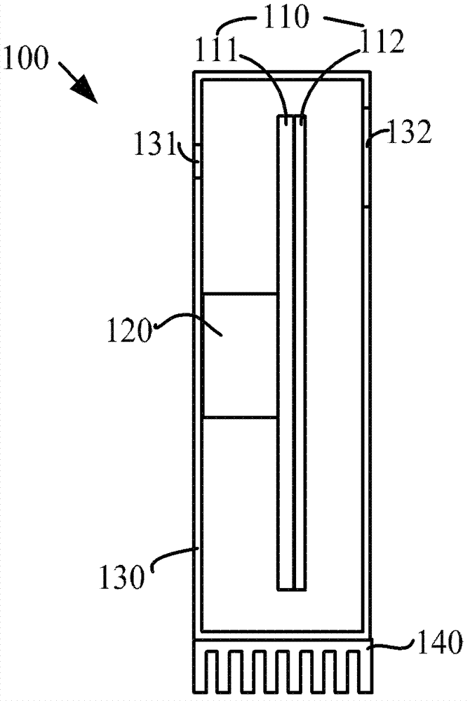
[0021] see figure 1 , figure 1 is a top view of an embodiment of the wavelength conversion device in the embodiment of the present invention. Such as figure 1 As shown, the wavelength conversion device 100 includes a wavelength conversion layer 110 , a driving device 120 , a box 130 and an external heat sink 140 .

[0022] The wavelength conversion layer 110 is used to absorb excitation light and generate stimulated light. The wavelength conversion sheet 110 includes a wavelength conversion material. The most commonly used wavelength conversion materials are phosphors, such as yttrium aluminum garnet (YAG) phosphors, which absorb blue light and are excited to produce yellow stimulated light. The wavelength conversion material may also be materials with wavelength conversion capabilities such as quantum dots and fluorescent dyes, and is not limited to phosphors. In many cases, wavelength conversion materials are often in powder or granular form, and it is difficult to dire...

Embodiment 2

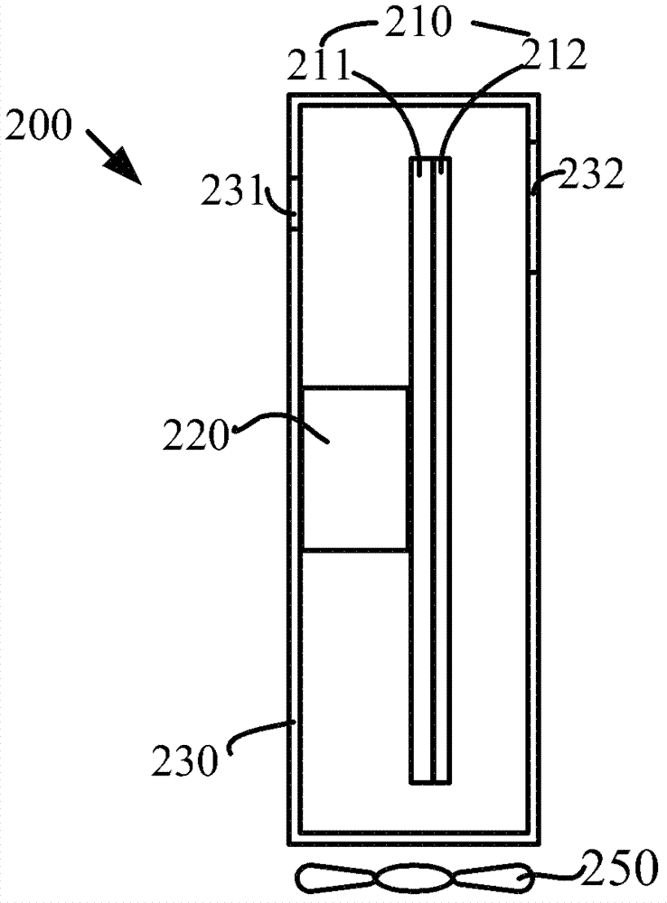
[0034] see figure 2 , figure 2 It is a top view of another embodiment of the wavelength conversion device in the embodiment of the present invention. Such as figure 2 As shown, the wavelength conversion device 200 includes a wavelength conversion layer 210 , a driving device 220 , a box 230 and an external fan 250 . The wavelength conversion layer 210 includes a substrate 211 and a wavelength conversion sheet 212 . The box 230 includes a first area 231 and a second area 232 .

[0035] This embodiment and figure 1 The difference of the illustrated embodiment is that in this embodiment, an external fan 250 is used instead figure 1 The external heat sink 140 in the box dissipates heat. The external fan 250 is disposed outside the box 230 . In the present invention, in order to distinguish the fans arranged outside and inside the box, the fans arranged outside and inside the box are respectively referred to as external fans and internal fans. It is easy to understand th...

Embodiment 3

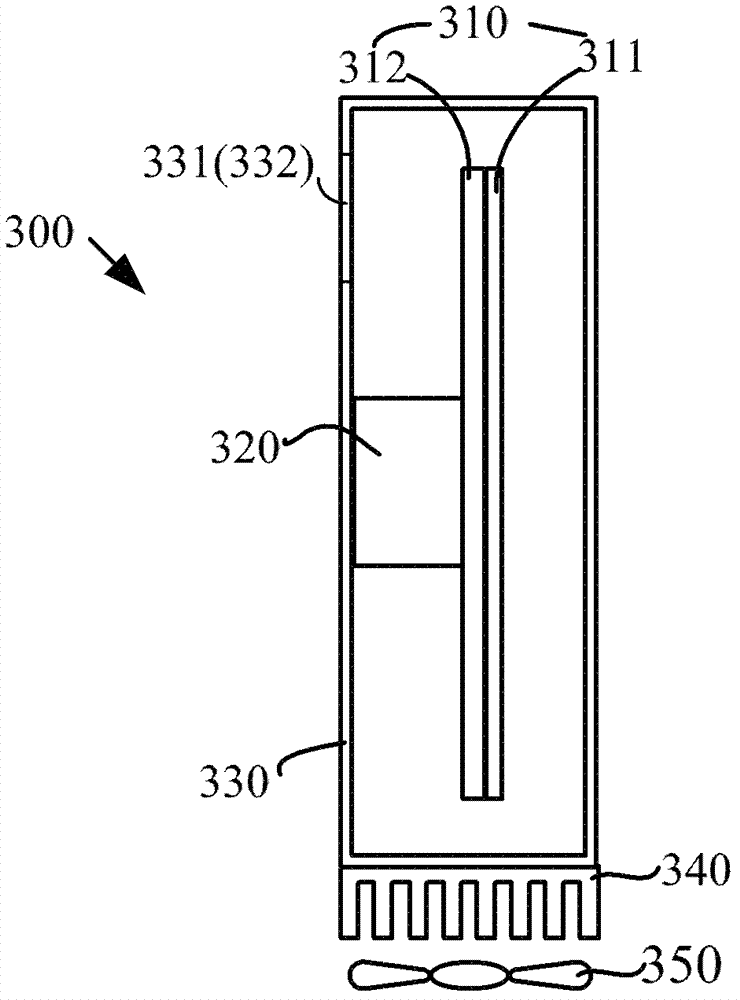
[0038] see image 3 , image 3 It is a top view of another embodiment of the wavelength conversion device in the embodiment of the present invention. Such as image 3 As shown, the wavelength conversion device 300 includes a wavelength conversion layer 310 , a driving device 320 , a box 330 , an external heat sink 340 and an external fan 350 . The wavelength conversion layer 310 includes a substrate 311 and a wavelength conversion sheet 312 . The box 330 includes a first area 331 and a second area 332 .

[0039] This embodiment and figure 1 The differences of the illustrated embodiment include the following two points:

[0040] (1) The wavelength conversion device 300 adopts a reflective type, that is, the incident light direction of the wavelength conversion device 300 is opposite to the outgoing light direction, so the first area 331 and the second area 332 are combined into the same area, and the wavelength conversion sheet 312 is located between the substrate 311 and ...


PUM


Abstract

The embodiment of the invention discloses a wavelength converter and a light-emitting device. The wavelength converter comprises a wavelength conversion layer for receiving exciting light and producing excited light, a driving device for driving the wavelength conversion layer to make periodical motion, a box for sealing the wavelength conversion layer and the driving device and comprising a first area for transmitting the exciting light to the wavelength conversion layer and a second area for transmitting the excited light, (and) an external fan arranged outside the box and used for cooling the box, and / or an external radiator arranged on the external surface of the box. According to the embodiment of the invention, the dustproof and radiating of a color wheel in the prior art are realized.

Description

technical field [0001] The invention relates to the technical field of light sources for illumination and display, in particular to a wavelength conversion device and a light emitting device. Background technique [0002] Patent US7547114 discloses a structure of a high-brightness light source, which comprises a rotating fluorescent pink wheel excited by the excitation light of the excitation light source. The fluorescent pink wheel includes a substrate, a fluorescent material and a driving device (such as a motor); the fluorescent material is coated on the substrate, and the substrate is fixed on the rotating shaft of the driving device. [0003] Since the conversion efficiency of fluorescent materials is often not higher than 80%, and often around 50%, fluorescent materials generate a lot of heat while emitting light, which in turn warms the fluorescent materials and even the entire color wheel, and finally reaches thermal equilibrium. As the intensity and power of the ex...

Claims


Application Information

Patent Timeline
Patent Type & Authority Applications(China)
IPC IPC(8): F21V9/10F21V14/08F21V31/03F21V29/02F21V9/40F21V29/54F21V29/67F21V29/76
Inventor 李景程李屹
Owner APPOTRONICS CORP LTD
Why Eureka
Try Eureka