Method of reducing network loss of micro power grid

A micro-grid and network loss technology, which is applied in the direction of electrical components, circuit devices, AC network circuits, etc., can solve the problems of increasing bus voltage limit conditions, increasing transmission line loss, and reducing network loss without considering micro-grid, so as to reduce calculation Quantity, guaranteed accuracy, and strong stability

Active Publication Date: 2013-01-02
HOHAI UNIV
View PDF6 Cites 4 Cited by
  • Summary
  • Abstract
  • Description
  • Claims
  • Application Information

AI Technical Summary

Problems solved by technology

②The loss of the transmission line increases significantly
However, the reactive power control strategy of the isolated grid described in the above-mentioned patent is only based on the traditional nine-zone diagram control strategy for reactive power compensation control, and the bus voltage limit condition is added. The main starting point is to improve the voltage stability of the microgrid, and it does not Consider the need to reduce network loss in microgrid operation

Method used


Image

  • Method of reducing network loss of micro power grid
  • Method of reducing network loss of micro power grid
  • Method of reducing network loss of micro power grid

Examples


Embodiment Construction

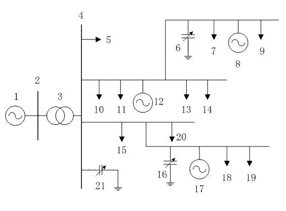
[0033] figure 1 What is shown is a schematic diagram of the basic structure of the microgrid of the present invention. In the figure, 1 is the system power supply, 2 is the busbar connecting the microgrid and the distribution network, 3 is the transformer connecting the microgrid and the distribution network, 4 is the busbar of the microgrid, 5, 7, 9, 10, 11, 13, 14, 15 , 18, 19, and 20 are loads, 6, 16, and 21 are reactive power compensation capacitors, and 8, 12, and 17 are distributed power sources. The microgrid is connected to the system power supply 1 through the bus 2 and the transformer 3. The microgrid bus 4 is connected to the load 5 and the reactive power compensation capacitor 21. The bus 4 is connected to two feeders, respectively connected to the corresponding distributed power supply and load. Wherein the reactive power compensation capacitor 6 and the reactive power compensation capacitor 16 are respectively connected to the two feeders. In particular, the in...


PUM


Abstract

The invention discloses a method of reducing network losses of a micro power grid. A reactive optimization model is established for the micro power grid, reactive compensation of a capacitor group in the micro power grid in the case of minimum active losses of a network is solved by an optimization algorithm, wherein the optimization algorithm comprises the following steps of: 1) generating an initialized group; 2) calculating a network loss value corresponding to each individual in the group, seeking the individual subjected to the minimum network loss, keeping the minimum network loss as an optimal value, and recording the position; and iterating and updating the positions of all individuals according to an updating formula, seeking the individual subjected to the minimum network loss, and keeping the minimum network loss as a new optimal value; and 3) comparing the new optimal value with the original optimal value, restoring the individual with the new optimal value to the position of previous iteration if the optimal value is updated, and outputting final optimization results after the iterative operation is finished. Compared with the prior art, the network losses of the micro power grid can be reduced, and the overall efficiency of utilization of electric energy can be improved. The selected optimization algorithm cannot be easily subjected to local optimization. Moreover, the number of equation parameters used in the iterative operation can be reduced, and the equation parameters used in the iterative operation can be adjusted conveniently and have stronger stability.

Description

technical field [0001] The invention relates to an energy-saving method for a microgrid, in particular to a method for reducing network loss in a microgrid. Background technique [0002] With the development of the national economy, the demand for electricity is growing rapidly, and the power sector is vigorously building large-scale centralized power sources such as thermal power, hydropower, and nuclear power, and ultra-high voltage long-distance transmission networks. However, with the continuous expansion of the grid scale, the operation cost of the ultra-large-scale power system is high and difficult, and it is difficult to adapt to the increasingly high safety and reliability requirements of users, as well as the diversified power supply needs. In recent years, there have been several large-scale power outages in the world, which fully exposed the vulnerability of the power grid. [0003] Micro-grid (micro-grid) refers to a small power generation and distribution syst...

Claims


Application Information

Patent Timeline
Patent Type & Authority Applications(China)
IPC IPC(8): H02J3/00H02J3/16
CPCY02E40/34Y02E40/30Y02P80/14
Inventor 刘皓明钱程晨李栅栅
Owner HOHAI UNIV
Why Eureka
Try Eureka