Reverse osmosis system

A technology of reverse osmosis and pressure exchanger, applied in the field of reverse osmosis system, can solve problems such as increased energy consumption and achieve the effect of reducing pressure loss

Active Publication Date: 2013-01-02
DANFOSS AS
View PDF5 Cites 3 Cited by
  • Summary
  • Abstract
  • Description
  • Claims
  • Application Information

AI Technical Summary

Problems solved by technology

Energy expenditure increases through higher salt concentration

Method used


Image

  • Reverse osmosis system
  • Reverse osmosis system
  • Reverse osmosis system

Examples


Embodiment Construction

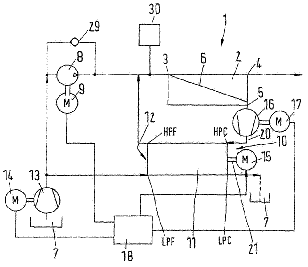
[0027] figure 1 is a schematic view of a reverse osmosis system 1, also known as a reverse osmosis plant or reverse osmosis plant.

[0028] The reverse osmosis system comprises a membrane unit 2 having an inlet 3 , a permeate outlet 4 and a concentrate outlet 5 . A membrane 6 is arranged between the inlet 3 and the permeate outlet 4 .

[0029] Of course, the membrane unit 2 can also have more than one inlet 3, one permeate outlet 4 and / or one concentrate outlet 5, and corresponding housings.

[0030] Via a high pressure pump 8 driven by a motor 9, the membrane unit 2 is supplied with feed water from a reservoir 7, eg the sea. The high-pressure pump 8 can be, for example, a piston pump. The motor 9 may be an electric motor controlled by a frequency converter. Thus, the high pressure pump 8 can be driven at variable speed and thus with variable delivery.

[0031] For reasons of simplification, the water from the reservoir 7 will be referred to simply as "feed water" in the ...


PUM


Abstract

The invention concerns a reverse osmosis system (1) with at least one membrane unit (2) comprising an inlet (3), a permeate outlet (4) and a concentrate outlet (5), a high-pressure pump (8) that is connected to the inlet (3), a pressure exchanger (11) comprising at least one high-pressure concentrate connection (HPC), and a booster pump. It is endeavoured to achieve the lowest possible energy consumption. For this purpose, the booster pump is made as a displacement pump (16) that is arranged between the concentrate outlet (5) and the high-pressure concentrate connection (HPC) of the pressure exchanger (11).

Description

technical field [0001] The invention relates to a reverse osmosis system having at least one membrane unit comprising an inlet, a permeate outlet and a concentrate outlet, the reverse osmosis system being connected to a high pressure pump of the inlet, comprising at least one pressure exchanger to which the high pressure concentrate is connected and a booster pump. Background technique [0002] Reverse osmosis systems serve the purpose of producing potable water, for example from brine or sewage, below forming the term "feed water". For this purpose, feed water is brought to a relatively high pressure, eg 80 bar or higher, by a high pressure pump and supplied to the inlet of the membrane unit. In this membrane unit is arranged a semi-permeable membrane which retains dirt or salts of the feed water and allows only clean water to pass through, called permeation. This increases the concentration of salt and dirt in the remaining feed water. Feed water with increased concentr...

Claims


Application Information

Patent Timeline
Patent Type & Authority Applications(China)
IPC IPC(8): B01D61/06
CPCB01D2313/243B01D61/06C02F1/441
Inventor W.弗雷德里克森E.豪嘉德L.N.朗马克P.奥尔森
Owner DANFOSS AS
Why Eureka
Try Eureka