Radiation imaging apparatus

A radiation imaging and radiation image technology, which is applied to imaging devices, diaphragms for radiation diagnosis, material analysis using radiation, etc., can solve the problems of undisclosed X-ray image detector arrangement relationship and other issues

Inactive Publication Date: 2013-01-09
FUJIFILM CORP
View PDF6 Cites 6 Cited by
  • Summary
  • Abstract
  • Description
  • Claims
  • Application Information

AI Technical Summary

Problems solved by technology

[0010] However, US Patent Application Publication 2011 / 0158493 does not disclose the arrangement relationship between the direction of the Moiré fringes of the Moiré image and the direction of the X-ray image detector

Method used


Image

  • Radiation imaging apparatus
  • Radiation imaging apparatus
  • Radiation imaging apparatus

Examples


no. 1 example

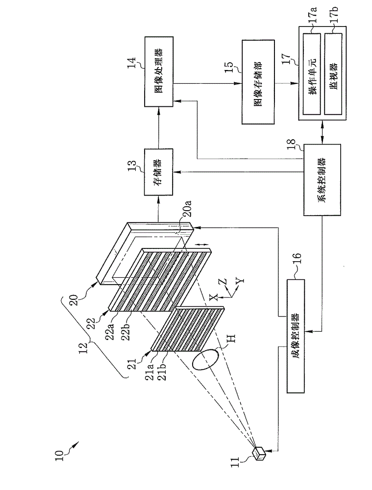
[0052] exist figure 1 Among them, a radiation imaging apparatus such as an X-ray imaging apparatus 10 is provided with an X-ray source 11 , an imaging section 12 , a memory 13 , an image processor 14 , an image storage section 15 , an imaging controller 16 , a console 17 and a system controller 18 . As known, the X-ray source 11 has a rotating anode type X-ray tube (not shown) and a collimator (not shown) for confining the X-ray field. The X-ray source 11 emits X-rays to the subject H.

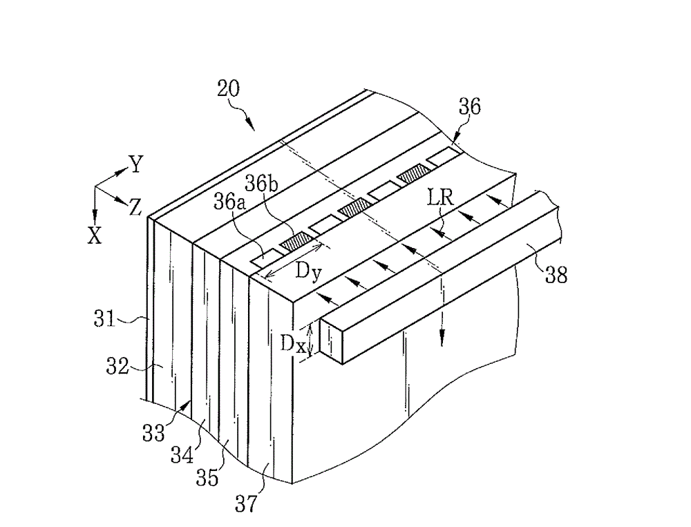
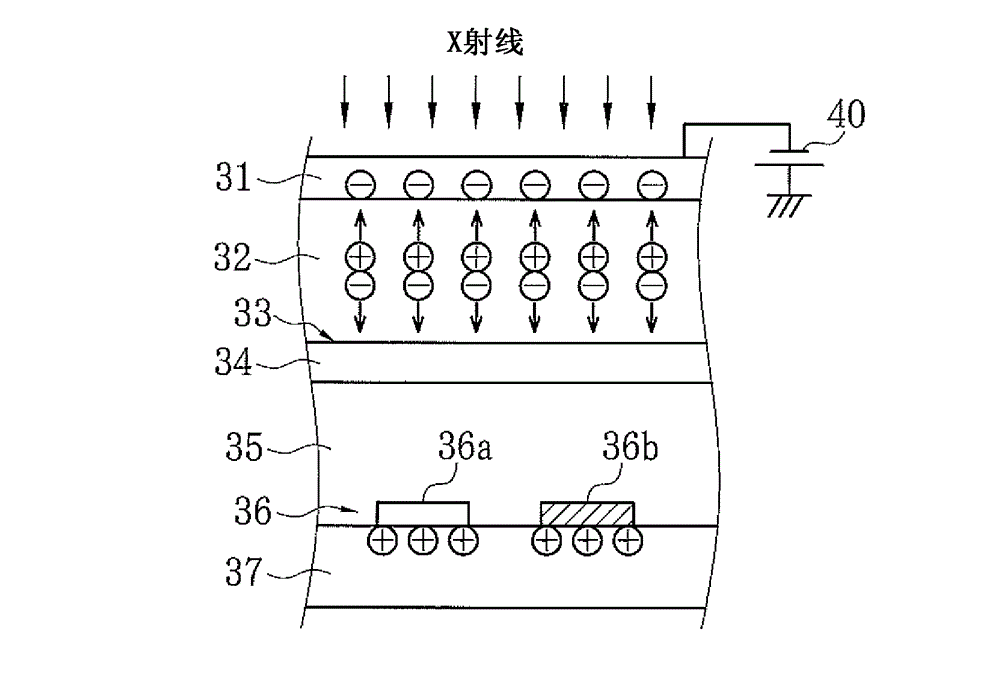
[0053] The imaging section 12 is provided with an X-ray image detector 20 , a first grating 21 and a second grating 22 . The first and second gratings 21 and 22 are absorption gratings, and face the X-ray source 11 in the Z direction which is the X-ray emission direction. Between the X-ray source 11 and the first grating 21, there is a space for arranging the subject H. The X-ray image detector 20 is an optical reading type flat panel detector. The X-ray image detector 20 is arranged behin...

no. 2 approach

[0129] Next, a second embodiment of the present invention is described. In the first embodiment, in order to cause moire fringes in the G2 image, one of the first and second gratings 21 and 22 is inclined relative to the other in a direction within the grating plane. On the other hand, in the X-ray imaging apparatus of the second embodiment, the first and second gratings 21 and 22 are not inclined. Instead, the positional relationship between the first and second gratings 21 and 22 (distance L 1 and L 2 ) or the grating pitch p of the first and second gratings 21 and 22 1 and p 2 to be slightly different from expression (1). As a result, moiré fringes are generated in the G2 image, such as Figure 17 shown in .

[0130] The pattern period p in the X direction of the G1 image in the position of the second grating 22 3 The grating pitch p from the second grating 22 2 Slightly shifted. Moiré fringes have a period T in the X direction expressed by Expression (15).

[013...

no. 3 approach

[0143] Next, a third embodiment of the present invention is described. In the first and second embodiments, the X-ray source 11 has a single focal point. On the other hand, in the third embodiment, as Figure 20 As shown in , a multi-slit (source grating) 23 disclosed in eg WO 2006 / 131235 is arranged immediately before on the emission side of the X-ray source 11 . Similar to the first and second gratings 21 and 22, the multi-slit 23 has a plurality of X-ray absorbing portions 23a and a plurality of X-ray transmitting portions 23b extending in the Y direction and arranged alternately in the X direction. Set the grating pitch p of the multi-slit 23 0 To basically satisfy the expression (19), where, "L 0 ” denotes the distance between the multi-slit 23 and the first grating 21.

[0144] p 0 = L 0 L 2 p 2 ...


PUM

PropertyMeasurementUnit
thicknessaaaaaaaaaa
thicknessaaaaaaaaaa
thicknessaaaaaaaaaa

Abstract

The invention refers to a radiation imaging apparatus, and specifically an X-ray imaging apparatus has first and second gratings, an X-ray image detector, and a differential phase image production section. The first grating passes X-rays emitted from an X-ray source to produce a first periodic pattern (G1 image). The second grating is disposed in a rotated state while being kept in parallel with the first grating. The second grating partly shields the G1 image to produce a second periodic pattern image (G2 image) with moire fringes. The X-ray image detector detects the G2 image to produce image data. The differential phase image production section produces a differential phase image based on the image data. The X-ray image detector has a difference in sharpness between two orthogonal directions within its detection surface, and is disposed such that one of the directions with the high sharpness crosses the moire fringes.

Description

technical field [0001] The present invention relates to a radiation imaging apparatus for obtaining an image based on a phase change of radiation caused by an object. Background technique [0002] When radiation such as X-rays passes through a substance, the X-rays are attenuated depending on the weight (atomic number) of elements constituting the substance and the density and thickness of the substance. Because of this property, X-rays are used as detectors for inspecting the inside of a subject in performing medical diagnosis and non-destructive inspection. [0003] Common X-ray imaging devices have an X-ray source for emitting X-rays and an X-ray image detector for detecting X-rays. The subject is placed between the X-ray source and the X-ray image detector. X-rays emitted from an X-ray source are attenuated by absorption by an object, and then incident on an X-ray image detector. Thus, the X-ray image detector detects an image based on a change in the intensity of X-r...

Claims


Application Information

Patent Timeline
Patent Type & Authority Applications(China)
IPC IPC(8): A61B6/00G01N23/04
CPCG01N23/04A61B6/484A61B6/00A61B6/06G21K2207/005
Inventor 桥本温之
Owner FUJIFILM CORP
Why Eureka
Try Eureka