

Vibratory spiral polisher
A vibrating screw, polishing machine technology, applied in surface polishing machine tools, grinding/polishing equipment, machine tools suitable for grinding workpiece edges, etc., can solve problems such as polishing occupation, and achieve the reduction of processing steps and polishing. time, the effect of improving the method of feeding and discharging
Inactive Publication Date: 2013-01-09
SHANGHAI UNIVERSITY OF ELECTRIC POWER
View PDF7 Cites 3 Cited by
- Summary
- Abstract
- Description
- Claims
- Application Information
AI Technical Summary
Problems solved by technology
[0003] The present invention is to provide a vibrating spiral polishing machine to achieve continuous feeding, conveying, polishing and discharging of parts, thereby solving the technical problems of time spent on parts polishing and continuous transmission of parts
Method used
View moreImage
Smart ImageViewing Examples

Examples
Embodiment
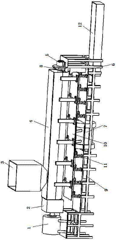
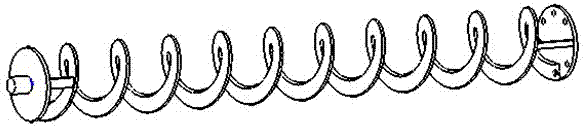
[0021] The feed motor 1 drives the reducer 2 to rotate, the reducer 2 is connected to the screw propulsion device 8 and transmits the power to the screw propulsion device 8 to make the screw propulsion device 8 rotate, the vibration motor 7 drives the material container 4 to perform high-frequency vibration through the vibrating frame 10, The parts enter the material container 4 from the feeding port 3 and pass through the material container 4 under the push of the screw propulsion device 8 shaftless spiral push rod, and the parts arrive at the bottom of the right port of the material container 4 under the push of the screw propulsion device 8 shaftless spiral push rod The discharge port 6 is exported by the discharge port 6.
Login to View More PUM
 Abstract
The invention relates to a vibratory spiral polisher. A vibrating grid is connected on the upper side of a frame through springs, a feed device is connected on the upper side of the vibrating grid, a vibrating machine is fixedly connected on the lower side of the vibrating grid, a feed inlet is arranged on the upper side of the feed device, a screw propulsion device is mounted in the feed device, a part machining space is formed between the feed device and the screw propulsion device, one end of the screw propulsion device is in rigid connection with a speed reducer and a feed motor, the other end of the screw propulsion device is connected with a supporting seat, a left port of the feed device is connected with the speed reducer and the feed motor in a floating manner, and a discharge port is arranged below a right port of the feed device. By the vibratory spiral polisher, time spent on part polishing can be reduced, continuous conveying of parts can be achieved, and production efficiency is improved greatly. By the aid of the continuous conveying process, the vibratory spiral polisher can be connected into an assembly line to achieve an assembly line operation mode of part forming, polishing and finish machining. Besides, a feeding and discharging mode is improved, inertial impact is alleviated, machining steps are decreased, and time spent on polishing is greatly decreased.
Description
technical field [0001] The invention relates to a vibration machine for removing burrs from parts, in particular to a vibration polishing machine. Background technique [0002] At present, industrial production is gradually developing in the direction of automation, informatization, and continuous production, and many productions have realized assembly line operations. With the advancement of society and technology, the requirements for the quality of parts are getting higher and higher. At the same time, manufacturers also require to increase the speed of parts processing, but there is still a lot of room for improvement in the processing efficiency of many parts. Generally speaking, there are burrs on the surface of many parts after processing and forming. The burrs need to be removed before the parts are used. Whether the deburring is efficient has a certain impact on the production and processing speed. Most of the polishing machines used in current industrial productio...
Claims
Login to View More Application Information
Patent Timeline
 Patent Type & AuthorityApplications(China)
IPC IPC(8): B24B31/06
Inventor陈乃超韩建
OwnerSHANGHAI UNIVERSITY OF ELECTRIC POWER