Biomass material conveying mechanism

A material transmission and biomass technology, applied in the field of biomass material transmission mechanism, can solve the problems of material conveying failure, discontinuous material conveying, poor fluidity, etc., to reduce power consumption and facilitate the extraction of materials.

Pending Publication Date: 2019-12-03
成都翠威新能源科技中心(有限合伙)
View PDF0 Cites 0 Cited by
  • Summary
  • Abstract
  • Description
  • Claims
  • Application Information

AI Technical Summary

Problems solved by technology

[0006] In view of the problem of poor fluidity of the materials such as garbage, wood chips, straw, and branches proposed above, when the above materials are transported, bridge arches or air pockets often occur due to the materials to be transported in the hopper, and the above bridge arches Or cavitation will not only cause discontinuous material delivery, but also cause technical problems of material delivery failure. The invention provides a biomass material delivery mechanism

Method used


Image

  • Biomass material conveying mechanism
  • Biomass material conveying mechanism

Examples


Embodiment 1

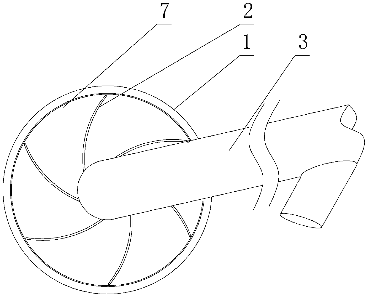
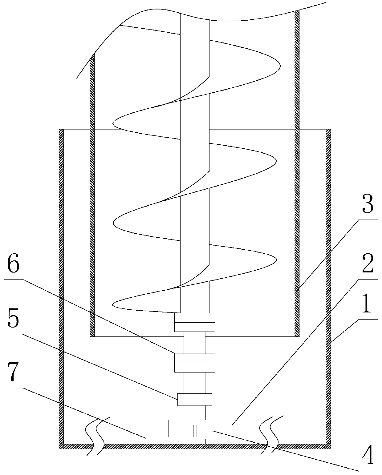
[0027] Such as figure 1 and figure 2 As shown, a biomass material transmission mechanism includes a hopper 1, and also includes a stirring mechanism installed in the hopper 1. The stirring mechanism includes a rotating shaft 4 installed at the bottom of the hopper 1, and a paddle is also installed on the rotating shaft 4. 2. The paddle 2 is an elastic piece made of elastic material, one end of the paddle 2 is fixed on the side of the rotating shaft 4, and when the paddle 2 is in a free state, the free end of the paddle 2 extends to the outside of the rotating shaft 4 In this way, the combination of the plectrum 2 and the rotating shaft 4 is in the shape of an open impeller; during the rotation of the plectrum 2, when the side of the plectrum 2 is resisted, the plectrum 2 can be wound on the rotating shaft 4.

[0028] In the prior art, if biomass materials such as straw and wood are used for gasification or pyrolysis, it is generally necessary to use a conveyor to transport t...

Embodiment 2

[0033] The present embodiment is further limited on the basis of embodiment 1, as figure 1 and figure 2 As shown, as the specific arrangement form of the rotating shaft 4 and the dial 2, it is set as follows: the axis of the rotating shaft 4 is perpendicular to the bottom surface of the hopper 1, the dial 2 is multi-piece, and the dial 2 is circular around the axis of the rotating shaft 4 Evenly distributed. Adopting this solution can effectively increase the frequency that the paddle 2 touches the material, and at the same time make the paddle 2 evenly act on the material, which is beneficial to the uniformity of material transmission.

[0034] As a material of the plectrum 2 that is wear-resistant and easy to obtain a suitable elastic coefficient, it is set that the elastic material is spring steel.

[0035] As a specific arrangement form of the plectrum 2, it is set as follows: when the plectrum 2 is in a free state, the protruding part of the plectrum 2 relative to the ...


PUM


Abstract

The invention discloses a biomass material conveying mechanism comprising a hopper, and a stirring mechanism that is mounted in the hopper; the stirring mechanism comprises a rotating shaft mounted atthe bottom of the hopper; a poking piece is further installed on the rotating shaft, the poking piece is an elastic piece made of an elastic material, one end of the poking piece is fixed to the sideface of the rotating shaft, and the free end of the poking piece extends out of the rotating shaft in a free state, so that a combined body composed of the poking piece and the rotating shaft is in an open impeller shape; in the rotating process of the poking piece, when the side face of the poking piece is subjected to resistance, the poking piece can be wound around the rotating shaft. The conveying mechanism can effectively prevent bridge arches or air holes from being formed in materials to be conveyed, and meanwhile the advantage of saving power consumption is realized.

Description

technical field [0001] The invention relates to the technical field of material transmission equipment, in particular to a biomass material transmission mechanism. Background technique [0002] With the rapid development of my country's social economy, the acceleration of urbanization and the rapid improvement of people's living standards, the garbage and waste generated in the process of urban production and life have also increased rapidly, and the situation of domestic garbage occupying land and polluting the environment has become more and more obvious. The massive increase of household garbage makes garbage disposal more and more difficult. In addition, a large amount of straw obtained in agricultural production, and a large amount of branches and sawdust obtained in wood production, one of the traditional methods is to use direct incineration to obtain heat for reuse, and the resulting environmental pollution and other problems have gradually caused social problems wid...

Claims


Application Information

Patent Timeline
Patent Type & Authority Applications(China)
IPC IPC(8): B65G47/18B65G33/14B65D88/68
CPCB65D88/68B65G33/14B65G47/18
Inventor 彭琪彭罡
Owner 成都翠威新能源科技中心(有限合伙)
Why Eureka
Try Eureka