Method and device of local heat treatment for thin-walled tubular parts

A local heat treatment and parts technology, applied in heat treatment furnaces, heat treatment equipment, quenching devices, etc., can solve the problems of insufficient local heat treatment, uneven heating, cracking of parts, etc., to overcome uneven heating, save production costs, improve The effect of production efficiency

Inactive Publication Date: 2013-01-09
GUIZHOU NORMAL UNIVERSITY
View PDF8 Cites 20 Cited by
  • Summary
  • Abstract
  • Description
  • Claims
  • Application Information

AI Technical Summary

Problems solved by technology

[0002] At present, most heat treatment devices are only suitable for overall treatment of workpieces, and there are few methods and devices for local heat treatment of workpieces
Especially for local heat treatment of small thin-walled parts, it is still an unbroken technical problem
When heat treating thin-walled parts, due to its small effective heating area and volume, there are still some problems in the prior art: a) The heat conduction is too fast during the heating process, and the heating area is not easy to control, especially in the local annealing process It is often easy to exceed the set annealing area; b) uneven heating can easily cause excessive local temperature differences, often part of the area is lower than the set temperature of heat treatment, while the temperature of other areas is too high, even causing parts to crack, failing to reach Requirements for partial heat treatment; c) Inaccurate control of the heat treatment process, poor repeatability, the operation process is often only based on worker experience, poor product quality stability in mass production, and low yield
Therefore, the existing local heat treatment methods for thin-walled parts are still not ideal enough to meet the needs of production and use.

Method used


Image

  • Method and device of local heat treatment for thin-walled tubular parts
  • Method and device of local heat treatment for thin-walled tubular parts

Examples


Embodiment Construction

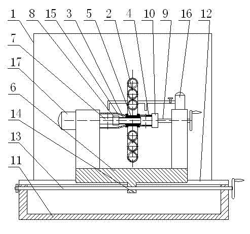
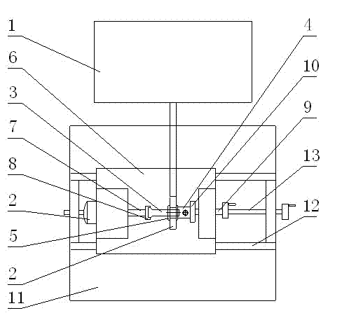
[0027] The present invention will be further described in detail below in conjunction with the accompanying drawings and embodiments.

[0028] Embodiments of the present invention: when implementing the method for local heat treatment of a thin-walled tubular part of the present invention, the high-frequency induction heating device in the prior art can be directly used to heat the thin-walled tubular part as the processed part. When performing heat treatment on parts of thin-walled tubular parts, heat treatment shall be carried out according to the following process:

[0029] a. Use a high-frequency induction heating device as the heating source, and determine the inner diameter and heating power of the high-frequency induction coil of the high-frequency induction heating device according to the outer diameter of the heating zone of the thin-walled tubular parts that requires local heat treatment, that is, the high-frequency induction coil. The inner diameter should be 5-30mm...


PUM


Abstract

The invention discloses a method and a device of local heat treatment for thin-walled tubular parts. A high-frequency induction heater is used as a heating source. The inner diameter of a high-frequency induction ring of the high-frequency induction heater is 5-30mm larger than the outer diameter of a heating-expected area of the thin-walled tubular part. The high-frequency induction ring with the heating power is capable of heating the heating-expected area of the thin-walled tubular part to required heating temperature in 10-60 seconds. When the thin-walled tubular part is subjected to local heat treatment, an auxiliary heating sleeve tool is used to sleeve the local heat area to be subjected to heat treatment. A gap between the inner surface of the heating sleeve tool and the sleeved position of the thin-walled tubular part is larger than 0.1mm and smaller than 1mm. The wall thickness of the heating sleeve tool is 2-10mm. The thin-walled tubular part is rotated around a center line of the high-frequency induction ring. The method and the method have the advantages that the heat area can be controlled effectively, heating is even, product quality is high and stable, operation is simple, manufacturing and using costs are low, and the method and the device are applicable to batch production, and the like.

Description

technical field [0001] The invention relates to a method and device for local heat treatment of thin-walled tubular parts, and belongs to the technical field of local heat treatment of thin-walled parts. Background technique [0002] At present, most heat treatment devices are only suitable for overall treatment of workpieces, and there are few methods and devices for partial heat treatment of workpieces. Especially for local heat treatment of small thin-walled parts, it is still an unbroken technical problem. When heat treating thin-walled parts, due to its small effective heating area and volume, there are still some problems in the prior art: a) The heat conduction is too fast during the heating process, and the heating area is not easy to control, especially in the local annealing process It is often easy to exceed the set annealing area; b) uneven heating can easily cause excessive local temperature differences, often part of the area is lower than the set temperature ...

Claims


Application Information

Patent Timeline
Patent Type & Authority Applications(China)
IPC IPC(8): C21D9/08C21D1/42C21D1/667
CPCY02P10/25
Inventor 刘静安儒强何英冯家杰王飞飞
Owner GUIZHOU NORMAL UNIVERSITY
Why Eureka
Try Eureka