Cylinder head for internal combustion engine
A cylinder head and internal combustion engine technology, applied to internal combustion piston engines, cylinder heads, combustion engines, etc., can solve the problem of catalyst warm-up performance degradation and achieve the effect of reducing the passage surface area
- Summary
- Abstract
- Description
- Claims
- Application Information
AI Technical Summary
Problems solved by technology
Method used
Image
Examples
Embodiment 1
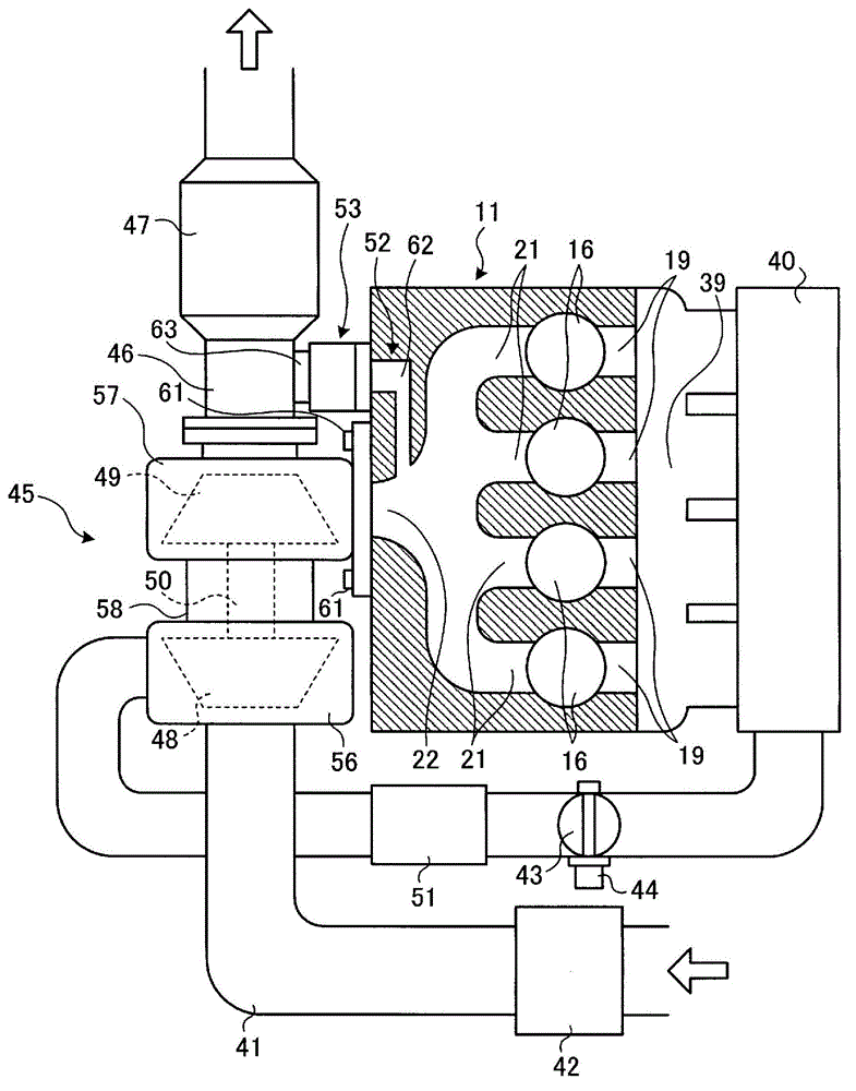
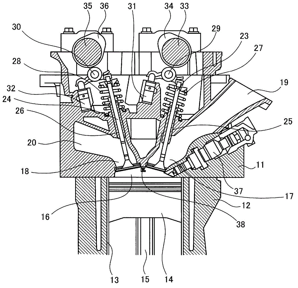
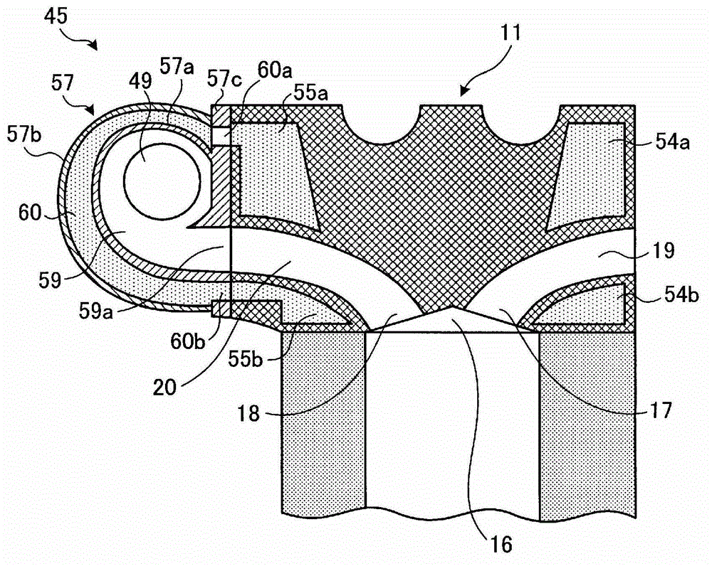
[0046] figure 1 is a schematic diagram showing a cylinder head of an internal combustion engine according to Embodiment 1 of the present invention, figure 2 is a longitudinal sectional view showing the internal combustion engine of Embodiment 1, image 3 is a longitudinal sectional view showing the cylinder head of the internal combustion engine of Embodiment 1, Figure 4 It is a sectional view showing the waist gate valve in the internal combustion engine of the first embodiment.
[0047] The internal combustion engine of embodiment 1 is an in-line 4-cylinder engine, such as figure 1 with figure 2 As shown, the cylinder head 11 is assembled with the cylinder block 12 at the lower part thereof, and is fastened by a plurality of fastening bolts not shown. A plurality of (four in the present embodiment) cylinder bores 13 are formed in a line on the cylinder block 12 , and a piston 14 is fitted to each cylinder bore 13 to move freely in the axial direction thereof. Further...
Embodiment 2
[0077] Figure 5 is a schematic diagram showing a cylinder head of an internal combustion engine according to Embodiment 2 of the present invention, Image 6 It is a longitudinal sectional view showing a cylinder head of the internal combustion engine of the second embodiment. In addition, components having the same functions as those described in the above-mentioned embodiments are denoted by the same reference numerals, and repeated explanations are omitted.
[0078] In the internal combustion engine of embodiment 2, as Figure 5 , Image 6 As shown, the cylinder head 71 is assembled with the cylinder block 12 at the lower part thereof, and is fastened by a plurality of fastening bolts not shown. A plurality of combustion chambers 16 are formed in the cylinder head 71 , and the intake port 17 opens opposite to the exhaust port 18 , and the intake passage 19 communicates with the intake passage 19 through the intake port 17 , and the exhaust passage 20 communicates with th...
Embodiment 3
[0088] Figure 7 is a schematic diagram showing a cylinder head of an internal combustion engine according to Embodiment 3 of the present invention, Figure 8 is a longitudinal sectional view showing the main parts of the cylinder head of the internal combustion engine of Embodiment 3 ( Figure 7 Ⅷ-Ⅷ section view). In addition, components having the same functions as those described in the above-mentioned embodiments are assigned the same reference numerals, and repeated explanations are omitted.
[0089] In the internal combustion engine of embodiment 3, as Figure 7 and Figure 8 As shown, a plurality of combustion chambers 82a, 82b, 82c, and 82d are formed in the cylinder head 81, and intake ports 83a, 83b, 83c, and 83d open opposite to exhaust ports 84a, 84b, 84c, and 84d. The air ports 83a, 83b, 83c, 83d communicate with four intake passages 85a, 85b, 85c, 85d, and communicate with one exhaust passage 86 through the exhaust ports 84a, 84b, 84c, 84d, and the exhaust pa...
PUM
 Abstract
Description
Claims
Application Information
 - R&D
- Intellectual Property
- Life Sciences
- Materials
- Tech Scout
- Unparalleled Data Quality
- Higher Quality Content
- 60% Fewer Hallucinations
Browse by: Latest US Patents, China's latest patents, Technical Efficacy Thesaurus, Application Domain, Technology Topic, Popular Technical Reports.
© 2025 PatSnap. All rights reserved.Legal|Privacy policy|Modern Slavery Act Transparency Statement|Sitemap|About US| Contact US: help@patsnap.com


