
Sub-aperture splicing interferometer system and method for measuring surface shape of optical lens

A technology of sub-aperture splicing and aperture splicing, which is applied in the field of optical detection, can solve the problems of air-film fluctuations in the air-floating guide, affecting the repeatability and measurement accuracy of the measurement, and the influence of the phase-shifting accuracy of the laser interferometer, and achieves absolute measurement, The effect of reducing airflow and temperature fluctuations

Inactive Publication Date: 2013-01-09
INST OF OPTICS & ELECTRONICS - CHINESE ACAD OF SCI
View PDF3 Cites 17 Cited by
  • Summary
  • Abstract
  • Description
  • Claims
  • Application Information

AI Technical Summary

Problems solved by technology

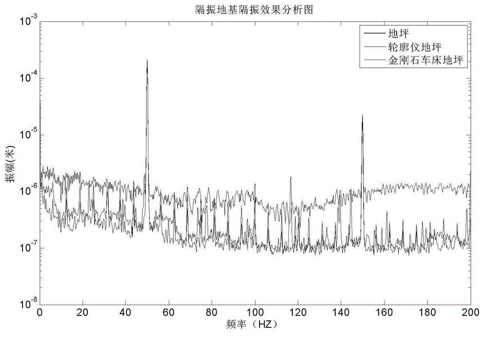
[0014] During the high-precision measurement process, environmental factors such as vibration, temperature, airflow fluctuations, and humidity will affect the repeatability and accuracy of the measurement
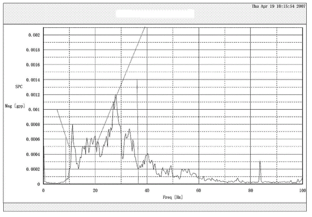
The positioning accuracy of the air-floating guide rail is high, but the air-floating guide rail has air film fluctuations, and there will be vibrations in the direction perpendicular to the mirror to be tested. The vibration frequency is within 100Hz, which has a great impact on the phase-shifting accuracy of the laser interferometer.

Method used


Image

  • Sub-aperture splicing interferometer system and method for measuring surface shape of optical lens
  • Sub-aperture splicing interferometer system and method for measuring surface shape of optical lens
  • Sub-aperture splicing interferometer system and method for measuring surface shape of optical lens

Examples


Embodiment Construction

[0047] In order to make the object, technical solution and advantages of the present invention clearer, the present invention will be described in further detail below in conjunction with specific embodiments and with reference to the accompanying drawings.

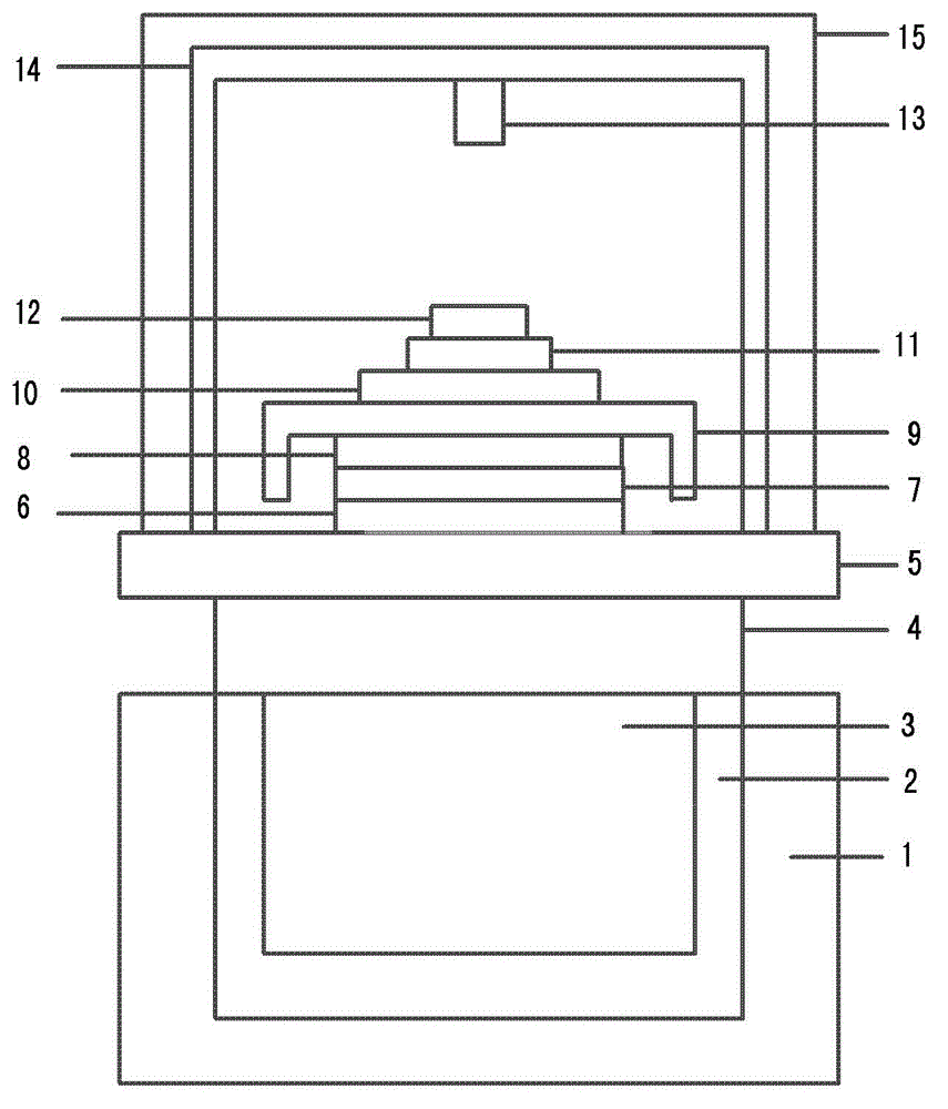
[0048] Such as figure 1 It shows the structural diagram of the device of the present invention, consisting of a ground vibration isolation unit 1, a partition layer 2, a filler 3, a first active vibration isolation unit 4, a platform 5, an air-floating guide rail 6, a first platform 7, and a second active vibration isolation unit 8. The second platform 9, the moving mechanism 10, the turntable 11, the optical lens to be tested 12, the laser interferometer 13, the truss frame 14, and the transparent cover 15. in:

[0049] An isolation layer 2 is placed in the pit of the ground vibration isolation unit 1, and the isolation layer 2 is used to isolate the surrounding underground materials;

[0050] A filler 3 is placed in t...


PUM


Abstract

The invention discloses a sub-aperture splicing interferometer system, which comprises a ground vibration insulating unit, a filler, an insulating layer, a first active vibration insulating unit, a platform, an air floatation guide rail, a first platform, a second active vibration insulating unit, a second platform, a moving mechanism, a revolving table, an optical lens to be tested, an air floatation guide rail, a truss and a transparent cover. According to the sub-aperture splicing interferometer mechanism with a vibration insulating effect, provided by the invention, the influence of ground vibration on measurement can be isolated through multilayer vibration insulating treatment; the glass cover is arranged, and nitrogen gas is charged into a measuring space, so that air current and temperature fluctuations are reduced; and the active vibration insulating unit is arranged above the air floatation guide rail, so that the influence of air film fluctuation on phase shift is reduced. Meanwhile, the mechanism can perform two-dimensional translation and rotation motions, so that absolute measurement can be realized in a splicing process. The invention further provides a method for measuring the surface shape of an optical lens by using the sub-aperture splicing interferometer system.

Description

technical field [0001] The invention belongs to the technical field of optical detection, and relates to a mechanism for measuring optical surface shapes by splicing sub-apertures. Background technique [0002] High-precision interferometric surface measurements are becoming more and more important, not only in the traditional field of optical manufacturing, but also in new fields such as the surface of optical discs or the surface of semiconductor crystals. There are more and more requirements for the detection accuracy of pv value in the sub-nanometer range. [0003] In the high-precision phase-shifting interferometer, the phase difference between the reference surface and the surface to be measured is mainly measured, and the measurement results include both the surface shape error of the surface to be measured and the error of the reference surface. The measurement repeatability accuracy of the phase-shifting interferometry method is very high, but the measurement accur...

Claims


Application Information

Patent Timeline
IPC IPC(8): G01B9/02G01B11/24
Inventor 贾辛徐富超谢伟民邢廷文
Owner INST OF OPTICS & ELECTRONICS - CHINESE ACAD OF SCI
Learn More