Automatic optic detecting system and method

A technology of automatic optical inspection and inspection platform

Inactive Publication Date: 2013-01-09
爱科维申科技(天津)有限公司
View PDF3 Cites 31 Cited by
  • Summary
  • Abstract
  • Description
  • Claims
  • Application Information

AI Technical Summary

Problems solved by technology

[0003] With the development of industrial castings, the installation density of mounting holes and surface mount parts is higher, and the traditional detection technology cannot adapt to the new quality control of workpieces and surface mount parts in terms of technology and speed. On-line production quality control and testing has brought great challenges
[0004] At present, workpieces and surface mount components have many types, different shapes, and different colors. Due to the design limitations of existing optical detection devices, it is impossible to be completely suitable for the detection of all surface mount components. Therefore, the existing optical detection The detection of surface mount components with different shapes and colors by the device leads to many problems and difficulties. Therefore, an automatic optical inspection system (AOI) for quality control of workpieces and surface mount components is needed to realize the detection of workpieces and The automatic detection of installation defects of its surface mount parts, so as to make up for the defects of the existing technology

Method used


Image

  • Automatic optic detecting system and method
  • Automatic optic detecting system and method
  • Automatic optic detecting system and method

Examples


Embodiment Construction

[0056] In order to understand the present invention more clearly, describe the present invention in detail in conjunction with accompanying drawing and embodiment:

[0057] Such as Figure 1 to Figure 16 As shown, the automatic optical detection system includes a mechanical system and a control system. The mechanical system is mainly composed of a bracket 1, a detection platform 2, an image acquisition box 3, a cylinder positioning component 4 and a workpiece pallet 5;

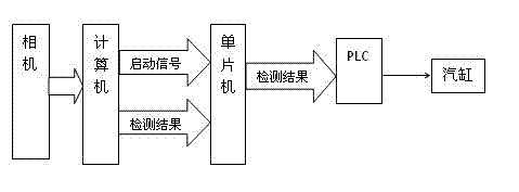
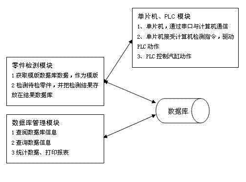
[0058] The control system is mainly composed of image acquisition components, light source controller, LED light source, single-chip microcomputer, PLC module and computer;

[0059] Bracket 1 is used as the base frame supporting detection platform 2 and cylinder positioning assembly 4. The detection platform 2 is fixed on the bracket 1. A rectangular opening is processed on the detection platform 2. A ball sliding platform 6 is installed on the opening, and the ball sliding platform 6 is used for the workpiece...


PUM


Abstract

The invention relates to an automatic optic detecting system and method. The system comprises a mechanical system and a control system, wherein the mechanical system is mainly composed of a support, a detecting platform, an image collecting box, a cylinder positioning assembly and a workpiece tray; and the control system is mainly composed of an image collecting assembly, a light source controller, an LED (Light Emitting Diode) light source, a singlechip, a PLC (Programmable Logic Controller) module and a computer. According to the method, template data of a to-be-detected workpiece are obtained through a part detecting module; a template database is established; the data of the template database is derived from the picture signals of a qualified workpiece; and the picture signals of the qualified workpiece are simultaneously collected by digital cameras at multiple positions and serve as a comparison standard of detecting the picture signals of the same to-be-detected workpiece. The automatic optic detecting system disclosed by the invention has the characteristics of non-contact, multidimensional detection, fastness, high efficiency, accuracy and the like and has the advantages that the workpiece and surface mounted components thereof can be effectively detected and managed and the automatic detection of installation defects of the workpiece and the surface mounted components of the workpiece is realized.

Description

technical field [0001] The invention relates to photoelectric detection technology, in particular to an automatic optical detection system and method, which are used to detect and manage workpieces and surface-mounted parts thereof, and realize automatic detection of installation defects of workpieces and surface-mounted parts thereof. Background technique [0002] In the past ten years, automatic optical inspection system (AOI) has been widely used in surface mount printed circuit board production lines. The application of the AOI system overcomes the disadvantages of manual inspection such as high labor intensity, eye fatigue, high missed inspection rate, and human factors, greatly improving the inspection speed and quality, improving production efficiency, and reducing production costs. [0003] With the development of industrial castings, the installation density of mounting holes and surface mount parts is higher, and the traditional detection technology cannot adap...

Claims


Application Information

Patent Timeline
Patent Type & Authority Applications(China)
IPC IPC(8): G01N21/88
Inventor 王忠强耿磊
Owner 爱科维申科技(天津)有限公司
Why Eureka
Try Eureka