Multi-channel signal amplifying circuit of low-duty ratio narrow pulse signal and control method

A signal amplification circuit and low duty ratio technology, applied in the direction of amplification control, pulse generation, gain control, etc., can solve the problem of output signal amplitude saturation, etc., and achieve narrow amplitude change range, fast response speed, and accurate gain control Effect

Active Publication Date: 2013-01-09
EAST CHINA INST OF OPTOELECTRONICS INTEGRATEDDEVICE
View PDF4 Cites 5 Cited by
  • Summary
  • Abstract
  • Description
  • Claims
  • Application Information

AI Technical Summary

Problems solved by technology

However, since the dynamic range of the received signal amplitude is up to 40dB, if the gain segmentation control method is adopted, if the number of gain segmentation stages is small, the goal will not be achieved. Not conducive to system assembly
[0003]The existing AGC amplifier, because its closed-loop control system uses multi-period integration to obtain the output signal amplitude, cannot accurately and timely obtain the multi-channel low duty ratio narrow pulse signal Therefore, it is not suitable for multi-channel low duty cycle narrow pulse signal amplification
[0004] In

Method used


Image

  • Multi-channel signal amplifying circuit of low-duty ratio narrow pulse signal and control method
  • Multi-channel signal amplifying circuit of low-duty ratio narrow pulse signal and control method
  • Multi-channel signal amplifying circuit of low-duty ratio narrow pulse signal and control method

Examples


Embodiment Construction

[0031] The preferred embodiments of the present invention will be described in detail below in conjunction with the accompanying drawings, so that the advantages and features of the present invention can be more easily understood by those skilled in the art, so as to define the protection scope of the present invention more clearly.

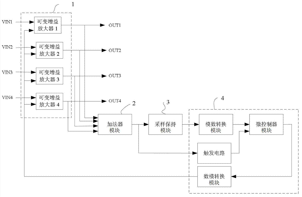
[0032] as attached figure 1 to attach Figure 9 As shown, the present embodiment is a multi-channel signal amplifying circuit of a low duty cycle narrow pulse signal, which includes

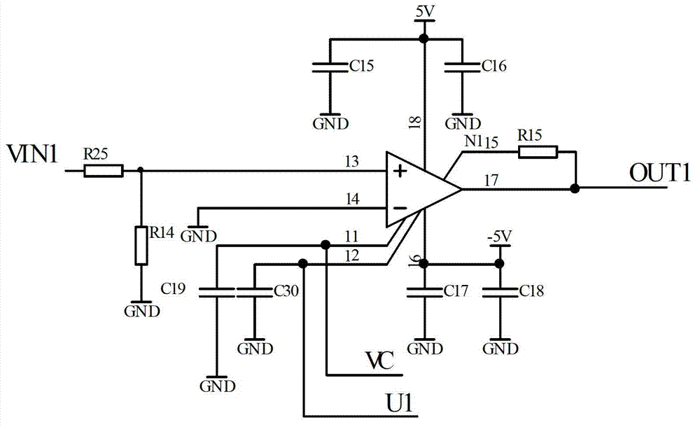
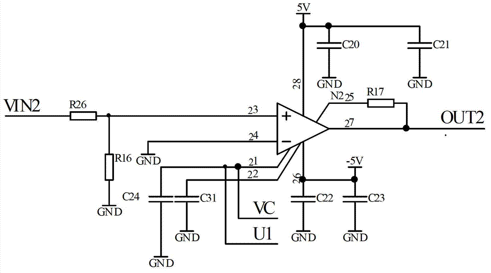
[0033] Variable gain amplifying circuit 1, the variable gain amplifying circuit comprises the variable gain amplifying circuit of multi-channel voltage control type, by the attached figure 1 The multi-channel signal amplifying circuit of the low-duty-ratio narrow pulse signal in the shown embodiment includes four 40dB variable gain amplifiers, and the four inputs of the four variable gain amplifiers are the four input signals of this embodiment, Four-way output of...


PUM


Abstract

The invention discloses a multi-channel signal amplifying circuit of a low-duty ratio narrow pulse signal and a control method. The multi-channel signal amplifying circuit of the low-duty ratio narrow pulse signal comprises a variable gain amplifying circuit, an adder circuit, a sampling keeping circuit and a master control unit module, wherein the master control unit module comprises a micro-control module; and an analogue-digital conversion module, a trigger circuit and a digital-analogue conversion module are integrated inside the micro-control module. According to the control method of the multi-channel signal amplifying circuit based on the low-duty ratio narrow pulse signal, the adder circuit can merge a plurality of paths of output signal amplitudes of the variable gain amplifying circuit into a path of signal; the micro-control module in the master control unit module judges the signal amplitude output by the adder circuit, and adjusts the voltage change output by the digital-analogue conversion module, so that the gain of a voltage-programmed variable gain amplifier is correspondingly changed, and the adder circuit outputs the pulse signal amplitude to stabilize at a set numerical value, so that a dynamic range output by the variable gain amplifier is reduced.

Description

technical field [0001] The invention relates to a hybrid integrated circuit in a laser detector and a control method, in particular to a multi-channel signal amplifying circuit and a control method of a low duty cycle narrow pulse signal. Background technique [0002] For some multi-channel signal processing systems using narrow pulse signals with low duty cycle, such as multi-channel laser detectors, since the dynamic range of the output signal reaches 40dB, the pulse width is hundreds of nanoseconds to several microseconds, and the period is as long as several milliseconds To tens of milliseconds, the signal must be amplified to an appropriate level by a variable gain amplifier before it can be processed by subsequent modules. However, since the dynamic range of the received signal amplitude is up to 40dB, if the gain segmentation control method is adopted, if the number of gain segmentation stages is small, the goal will not be achieved. Not conducive to system assembly....

Claims


Application Information

Patent Timeline
IPC IPC(8): H03K3/017H03G3/20
Inventor 高加林薛海英杨翠侠
Owner EAST CHINA INST OF OPTOELECTRONICS INTEGRATEDDEVICE
Why Eureka
Try Eureka