Superconducting magnet device

A technology of superconducting magnets and shielding coils, applied in superconducting magnets/coils, superconducting parts, measuring devices, etc., can solve problems such as large labor

Inactive Publication Date: 2013-01-09
JAPAN SUPERCONDUCTOR TECH
View PDF9 Cites 16 Cited by
  • Summary
  • Abstract
  • Description
  • Claims
  • Application Information

AI Technical Summary

Problems solved by technology

However, in this method, when changing the position of the magnetic sheet pasted once on the inner peripheral wall of the casing during the corre

Method used


Image

  • Superconducting magnet device
  • Superconducting magnet device
  • Superconducting magnet device

Examples


no. 1 Embodiment approach

[0091] (Superconducting magnet device)

[0092] figure 1 It is a schematic diagram showing the whole superconducting magnet device 1 according to the first embodiment of the present invention. Such as figure 1 As shown, the superconducting magnet device 1 of this embodiment has a casing 1a, an introduction part 1b, and an exhaust part 1c.

[0093] Regarding the case 1a, the outer shape is formed in a cylindrical shape having a through-hole 1d. The through hole 1d is concentrically formed in the case 1a. That is, the housing 1a and the through-hole 1d have a common central axis Z ( figure 1 double dotted line). In this embodiment, the superconducting magnet device 1 is installed so that the central axis Z is parallel to the horizontal direction via a supporting mechanism (not shown) supporting the lower surface of the case 1a. The casing 1a is hollow, and forms a vacuum chamber 3 in which the hollow space is a vacuum. The vacuum chamber 3 of the casing 1a is provided wit...

no. 2 Embodiment approach

[0153] Next, a second embodiment of the present invention will be described with reference to the drawings.

[0154] (Configuration of Superconducting Magnet Device)

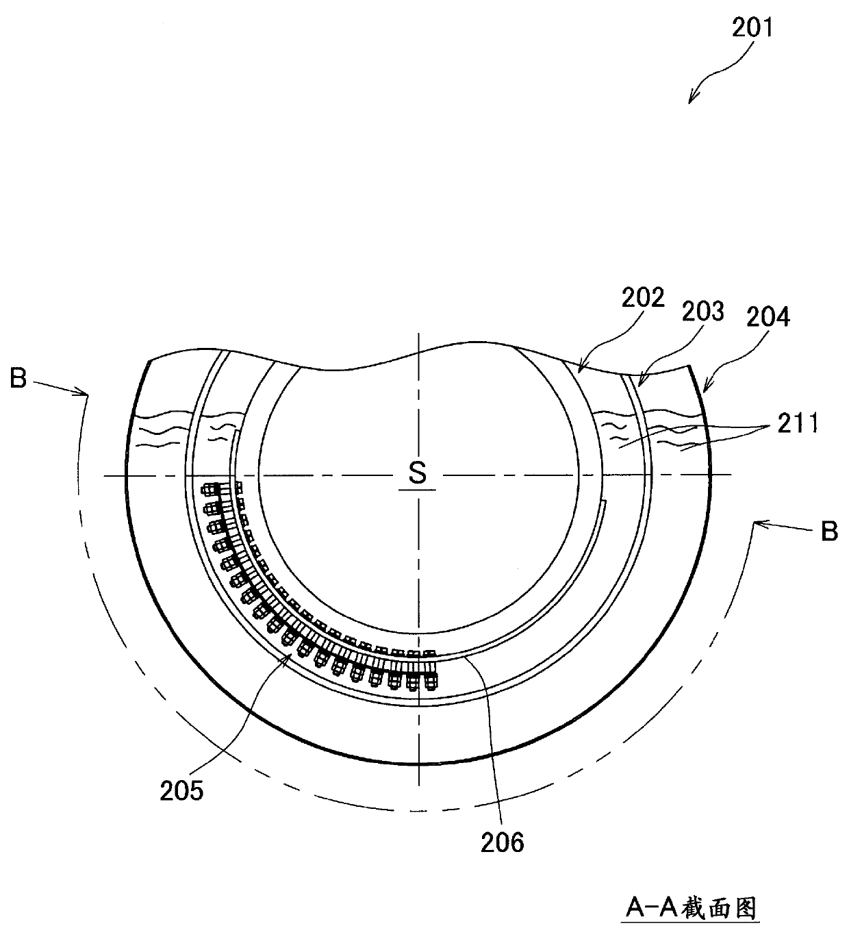
[0155] Such as Figure 6 and Figure 7 As shown, the superconducting magnet device 201 of this embodiment includes a main coil 202 , a shield coil 203 arranged outside the main coil 202 coaxially, and a helium container 204 arranged outside the shield coil 203 and containing liquid helium 211 . In the gap between the main coil 202 and the shield coil 203, a protective resistor 205 according to the present invention is arranged.

[0156] The main coil 202 is a coil for generating a predetermined magnetic field in the bore space S. As shown in FIG. In addition, the shield coil 203 is a coil for generating a magnetic field for reducing a leakage magnetic field leaked from the superconducting magnet device 201 to the outside.

[0157] The main coil 202 has five superconducting coils 208 a to 208 e and a bobbin 2...

no. 3 Embodiment approach

[0185] Next, a third embodiment of the present invention will be described with reference to the drawings.

[0186] Figure 13 is a schematic diagram showing a cross section of a superconducting magnet device 301 according to an embodiment of the present invention. Figure 14 yes Figure 13 A-A line sectional view. Figure 15 It is an explanatory diagram of the vicinity of the current socket in the state where the current lead is not installed.

[0187] (Superconducting magnet device 301)

[0188] Such as Figure 13 and Figure 14 As shown, the superconducting magnet device 301 of this embodiment has a vacuum container 302 with a double-tube structure, a refrigerant container 303 with a double-tube structure housed in the vacuum container 302, a radiation shield 340 with a double-tube structure, and a double-tube structure. A hollow cylindrical coil former 304 inside the refrigerant container 303 . In addition, the vacuum container 302, the refrigerant container 303, th...


PUM

PropertyMeasurementUnit
The inside diameter ofaaaaaaaaaa
Axial lengthaaaaaaaaaa

Abstract

Provided is a superconducting magnet device, wherein the superconducting magnet device can be miniaturized by miniaturizing a cooling chamber. Specifically provided is a superconducting magnet device comprising a cylindrical main former (13) on which a main coil (5) is wound, a cylindrical shield former (15) on which a shield coil (6) is wound and which is provided concentrically with the main former (13) so as to cover the outer side in the radial direction of the main former, a cylindrical external cylinder (18) which is provided concentrically with the main former (13) so as to cover the shield former (15), and a pair of end plates (14a, 14b) which forms a cooling chamber (2) by sealing the respective both ends in the axial direction of the main former (13) and the external cylinder (18); and is concentrically provided with annular positioning mechanisms that are in contact with the respective both ends in the axial direction of the main former (13), the shield former (15), and the external cylinder.

Description

technical field [0001] The invention relates to a superconducting magnet arrangement with a cooling chamber containing a cooling medium. Background technique [0002] Generally, regarding a superconducting magnet device, a superconducting magnet is composed of a main coil and a shielding coil. The main coil generates a magnetic field mainly in the magnetic field space and is wound around the main coil frame. The shielding coil suppresses the leakage of the magnetic field generated by the main coil to the It is outside the device and wound on a shielding coil frame. Such a superconducting magnet is installed and cooled in a cooling chamber containing a cooling medium. [0003] As such a superconducting magnet device, for example, a device as described in Patent Document 1 is known. In Patent Document 1, a superconducting magnet device is disclosed, which is equipped with a main coil, a shield coil, and a supporting member in a cooling chamber. The bobbins are arranged subs...

Claims


Application Information

Patent Timeline
IPC IPC(8): H01F6/00A61B5/055H01F6/02H01L39/04
CPCH01F6/02G01R33/3815G01R33/421H01F6/04
Inventor 竹田雅详伊藤聪齐藤一功I.米纳米宫田齐
Owner JAPAN SUPERCONDUCTOR TECH
Why Eureka
Try Eureka