Supercharge Your Innovation With Domain-Expert AI Agents!

Reduced-pressure distiller with high-position feeding and low-position collecting functions

A distiller and feeding technology, applied in the field of high-level feeding and low-level collection vacuum distiller, can solve the problems of high processing cost, long maintenance period, low processing added value, etc., achieve high-efficiency low-level collection, reduce heating energy consumption, The effect of suppressing short-circuit evaporation

Inactive Publication Date: 2013-01-16
唐山山岛石油化学有限公司
View PDF4 Cites 4 Cited by
  • Summary
  • Abstract
  • Description
  • Claims
  • Application Information

AI Technical Summary

Problems solved by technology

The disadvantages of this device are: due to its high compactness, high precision and miniaturization, it is difficult to achieve a long-term high-yield processing mode, it is not suitable for processing high boiling point, high heat sensitivity requirements, more impurities and low processing added value Otherwise: because the radial distance between the outer tube wall of the condenser tube and the inner wall of the cylinder is only 3.6cm ~ 4.2cm, there are upper and lower flanges, The rotating cage device composed of columns and scraper strips makes it very easy for the liquid droplets to splash from the inner wall of the cylinder to the outer tube wall of the condenser tube during feeding and rotating work, thereby forming a short-circuit evaporation (not vaporized and collected by the distillate collection system); because the inner wall of the jacket cylinder is both a heat release surface and an evaporation surface, it is bound to be absorbed by the generated solid phase within a short working time The compact and precise space of the device is polluted and destroyed, so that the device enters a longer maintenance cycle in a shorter working time
Due to the miniaturization of the device, the processing efficiency of the device is bound to be low
Due to the complex structure of the device, the manufacturing cost and maintenance cost of the device will inevitably be too high
[0014] To sum up, due to the long maintenance cycle of the device, the production cycle of the device is bound to be shortened, coupled with factors such as low processing efficiency, which will eventually lead to high processing costs and it is difficult to reflect the economic benefits of liquid material processing

Method used


Image

  • Reduced-pressure distiller with high-position feeding and low-position collecting functions
  • Reduced-pressure distiller with high-position feeding and low-position collecting functions
  • Reduced-pressure distiller with high-position feeding and low-position collecting functions

Examples


Embodiment 1

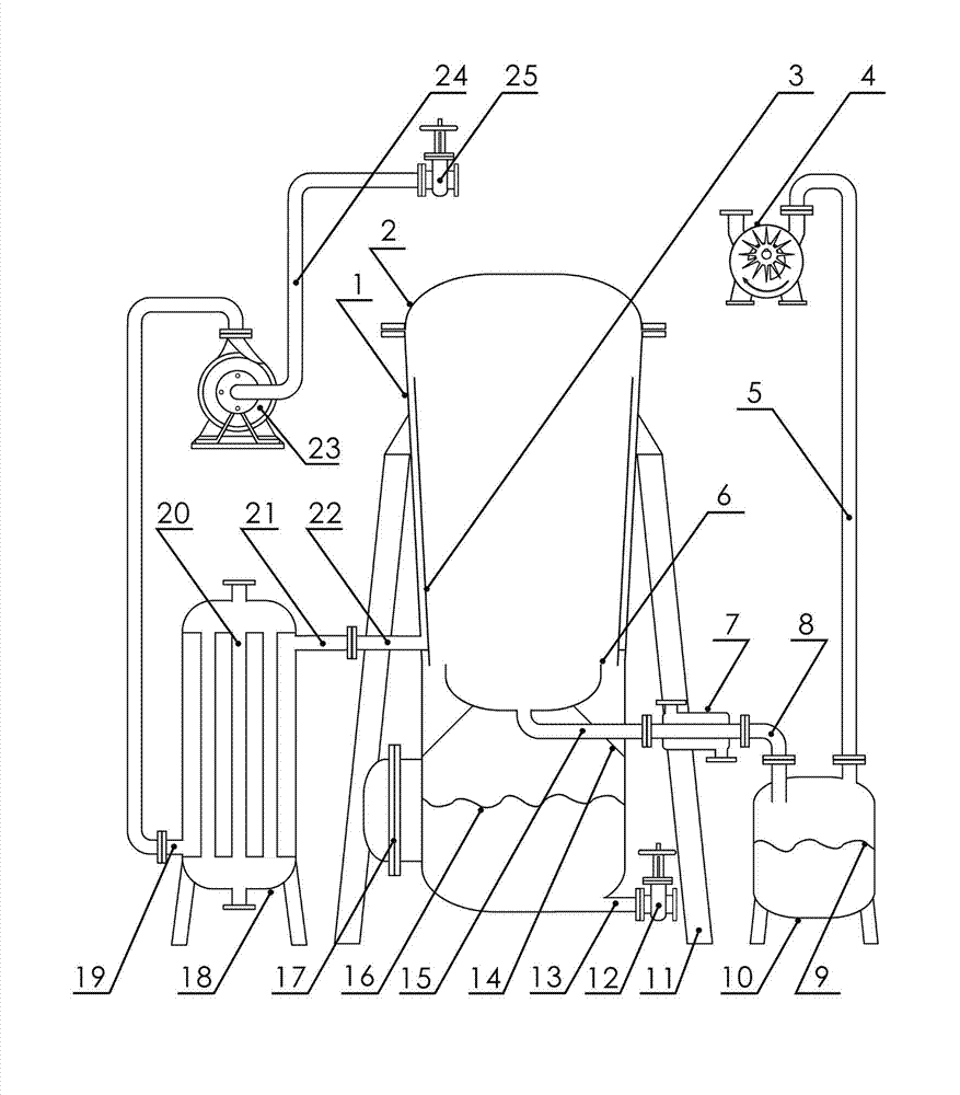
[0037] see figure 1 , figure 1 Middle: 1-evaporator shell, 2-top cover, 3-interlayer wall, 4-vacuum pump, 5-exhaust gas discharge pipeline 5, 6-guidance tank, 7-condenser, 8-distillate collection pipeline, 9 -Liquid phase distillate, 10-distillate collection tank, 11-evaporator support, 12-residual liquid discharge valve, 13-residual liquid discharge port, 14-drainage groove bracket, 15-drainage pipe, 16- Residual liquid, 17-manhole, 18-heater, 19-material liquid inlet, 20-exothermic body core tube, 21-heated material liquid outlet, 22-feed pipe, 23-material liquid delivery pump, 24-material Liquid input pipeline, 25-feeding valve.

[0038] In this embodiment, the evaporator shell 1 is a vertical structure tank container with an upper cover 2, the main body of the tank container and the upper cover 2 form a closed evaporation chamber, and the main body of the tank container is installed on the evaporator On the device support 11, and the main body of the tank container ha...

Embodiment 2

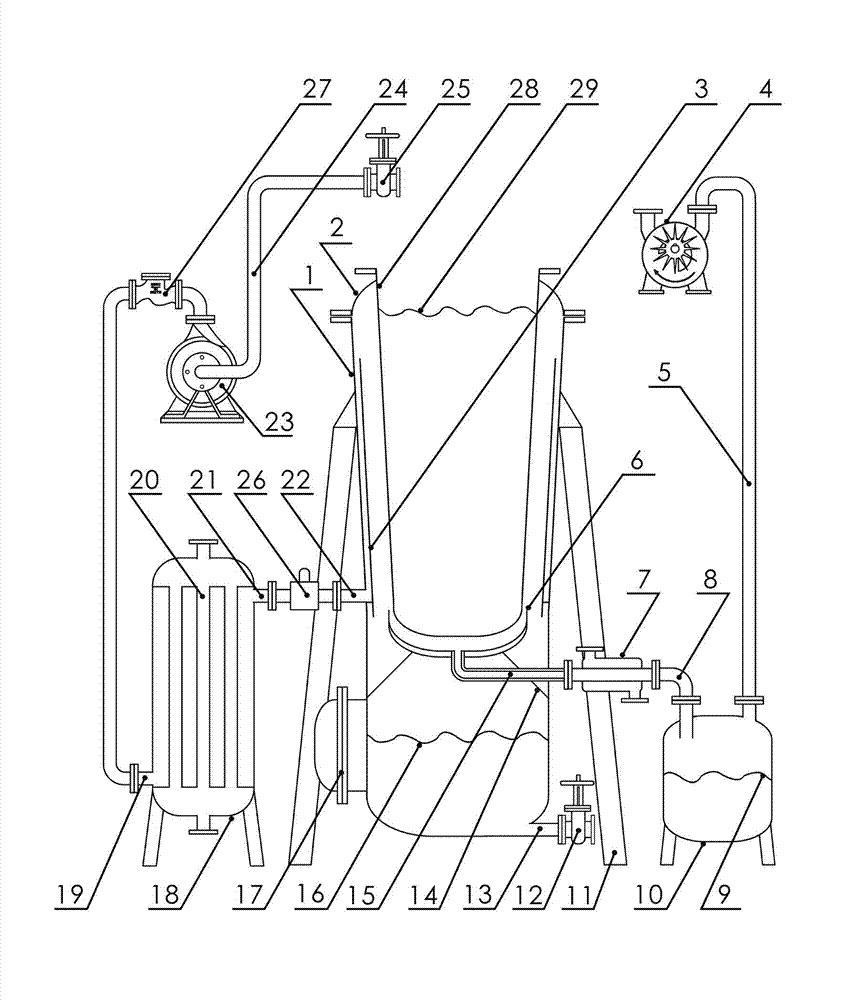
[0058] see figure 2 , figure 2 Middle: 1-evaporator shell, 2-top cover, 3-interlayer wall, 4-vacuum pump, 5-exhaust gas discharge pipeline, 6-guidance tank, 7-condenser, 8-distillate collection pipeline, 9- Liquid phase distillate, 10-distillate collection tank, 11-evaporator support, 12-residual liquid discharge valve, 13-residual liquid discharge port, 14-diversion groove bracket, 15-drainage pipe, 16-residual Liquid, 17-manhole, 18-heater, 19-material liquid inlet, 20-exothermic core tube, 21-heated material liquid outlet, 22-feed pipe, 23-material liquid delivery pump, 24-material liquid Input pipeline, 25-feeding valve, 26-barostat, 27-one-way valve, 28-cold trap, 29-cooling medium.

[0059] The difference between embodiment 2 and embodiment 1 only lies in:

[0060] The evaporator shell 1 is a vertical structure tank container with an opening at the upper end, and the tank container has a thick top and a thin bottom structure.

[0061] The inner cavity of the evapor...

Embodiment 3

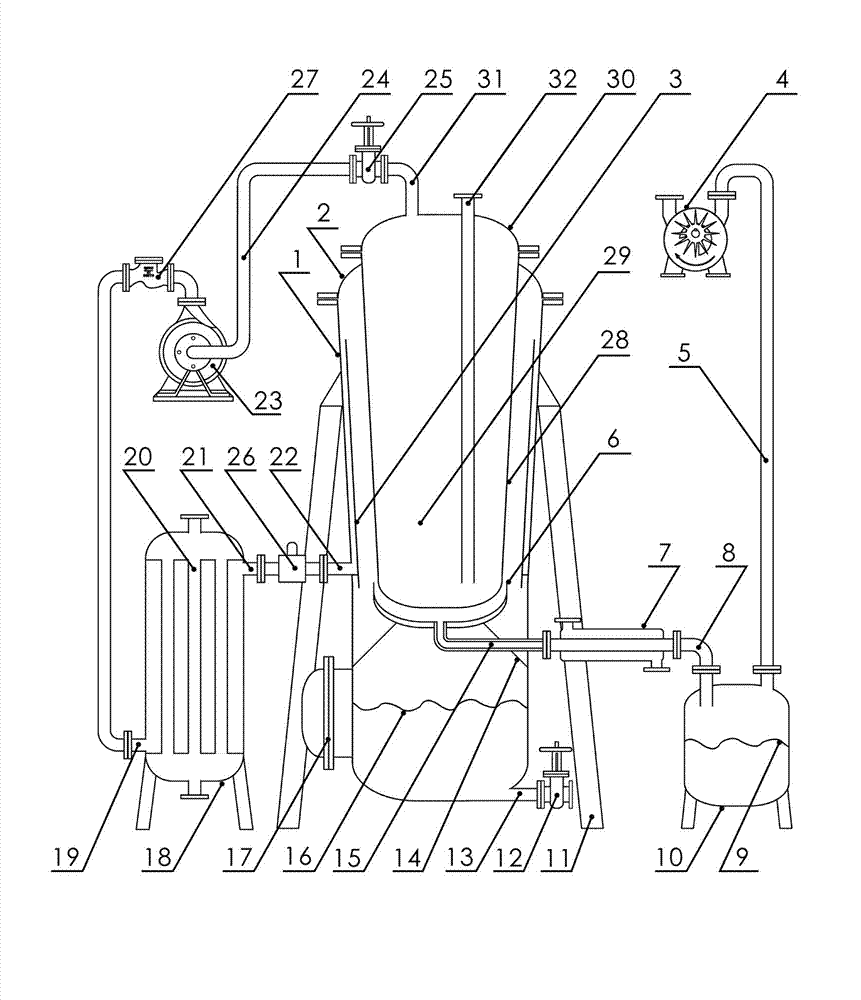
[0077] see image 3 , image 3 Middle: 1-evaporator shell, 2-top cover, 3-interlayer wall, 4-vacuum pump, 5-exhaust gas discharge pipeline, 6-guidance tank, 7-condenser, 8-distillate collection pipeline, 9- Liquid phase distillate, 10-distillate collection tank, 11-evaporator support, 12-residual liquid discharge valve, 13-residual liquid discharge port, 14-diversion groove bracket, 15-drainage pipe, 16-residual Liquid, 17-manhole, 18-heater, 19-material liquid inlet, 20-exothermic core tube, 21-heated material liquid outlet, 22-feed pipe, 23-material liquid delivery pump, 24-material liquid Input pipeline, 25-feeding valve, 26-barostat, 27-one-way valve, 28-cold trap, 29-cooling medium, 30-cold trap upper cover, 31-cooling medium outlet, 32-cooling medium inlet.

[0078] The difference between embodiment 3 and embodiment 1 and embodiment 2 only lies in:

[0079] The cold trap 28 and the cold trap upper cover 30 form a conical cylinder whose upper and lower ends are closed,...


PUM


Abstract

The invention relates to the filed of reduced-pressure distillation of organic materials such as used lubricant oil, in particular to a reduced-pressure distiller with high-position feeding and low-position collecting functions. The reduced-pressure distiller comprises an evaporator shell, a feed liquid heating mechanism consisting of a feed liquid input pipeline, a feed liquid delivery pump and a heater, and a distillate cooling and collecting reduced-pressure mechanism consisting of a condenser, a distillate collecting pipeline, a distillate collecting tank and a vacuum pump; an annular feed liquid interlayer channel formed by an interlayer wall and the side wall of the evaporator shell is installed in a sealed evaporating cavity which is arranged at the middle upper part in the evaporator shell; the upper end of the annular feed liquid interlayer channel is communicated with the sealed evaporating cavity in an opening manner; the side end of the annular feed liquid interlayer channel is communicated with a heated feed liquid outlet arranged at the upper end of the heater through a feed pipe extended from the side wall of the evaporator shell; a diversion trench is installed below the annular feed liquid interlayer channel; and the bottom of the diversion trench is connected with a diversion pipe and is communicated with the distillate cooling and collecting reduced-pressure mechanism through the diversion pipe. The reduced-pressure distiller provided by the invention can restrain pyrolysis degree of heated feed liquid so as to reduce heating energy loss and improve work efficiency.

Description

technical field [0001] The invention relates to the field of vacuum distillation of organic materials such as waste lubricating oil, in particular to a vacuum distiller for high-level feed and low-level collection. Background technique [0002] Vacuum distillation is a distillation method that reduces the energy saving of the boiling point of the feed liquid and suppresses the pyrolysis of the distillation feed liquid by reducing the pressure. The degree and production efficiency are currently the focus of attention of those skilled in the distillation field. [0003] Known vacuum distillation units are generally Figure 4 The structure shown, its working principle is briefly described as follows: [0004] Feed liquid (material to be purified by distillation) 4 is injected into the evaporator shell 1 placed on the evaporator support 2 through the feed valve 10 and the feed pipeline 9, and the injection volume accounts for about the volume of the evaporator shell 1 about on...

Claims


Application Information

Patent Timeline
Patent Type & Authority Applications(China)
IPC IPC(8): B01D3/10
Inventor 吴国存冯斌
Owner 唐山山岛石油化学有限公司
Features
  • R&D
  • Intellectual Property
  • Life Sciences
  • Materials
  • Tech Scout
  • Unparalleled Data Quality
  • Higher Quality Content
  • 60% Fewer Hallucinations
Learn More