Crushing type blockage prevention device

An anti-clogging and crushing technology, applied in grain processing, etc., can solve the problems of large temperature difference loss of water source, high operating cost, incomplete filtration, etc., and achieve the effect of low operating cost, simple process and reasonable structural design

Active Publication Date: 2013-01-16
HARBIN INST OF TECH
View PDF6 Cites 11 Cited by
  • Summary
  • Abstract
  • Description
  • Claims
  • Application Information

AI Technical Summary

Problems solved by technology

[0003] The purpose of the present invention is to solve the problem of incomplete filtration, cumbersome cleaning, large temperature difference loss of water source and high operating cost in the process of processing large-grained dirt and sundries in the sewage entering heat exchange equipment and other equipment using the prior art. problem, and then provide a broken anti-clogging device

Method used


Image

  • Crushing type blockage prevention device
  • Crushing type blockage prevention device
  • Crushing type blockage prevention device

Examples


specific Embodiment approach 1

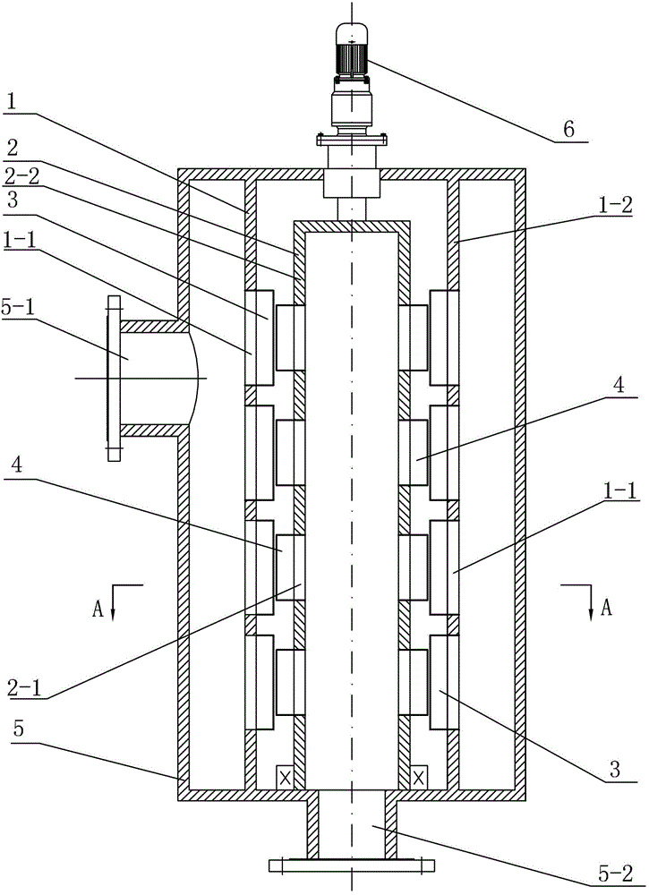
[0008] Specific implementation mode one: combine Figure 1 to Figure 5 Describe this embodiment, a crushing anti-clogging device of this embodiment includes a fixed outer cylinder 1, a rotating inner cylinder 2, an outer shell cylinder 5, a drive device 6, a plurality of inner blades 4 and a number of inner blades 4 consistent with A plurality of outer blades 3, the rotating inner cylinder 2 and the fixed outer cylinder 1 are respectively arranged in the shell cylinder 5, the fixed outer cylinder 1 is set outside the rotating inner cylinder 2, the fixed outer cylinder 1 is connected with the shell cylinder 5, and the shell cylinder 5. The fixed outer cylinder 1 and the rotating inner cylinder 2 are arranged coaxially. A driving device 6 is provided on the upper end surface of the shell cylinder 5. The driving end of the driving device 6 is connected with the rotating inner cylinder 2. The driving device 6 is used to drive the rotating inner cylinder. When the cylinder 2 rotate...

specific Embodiment approach 2

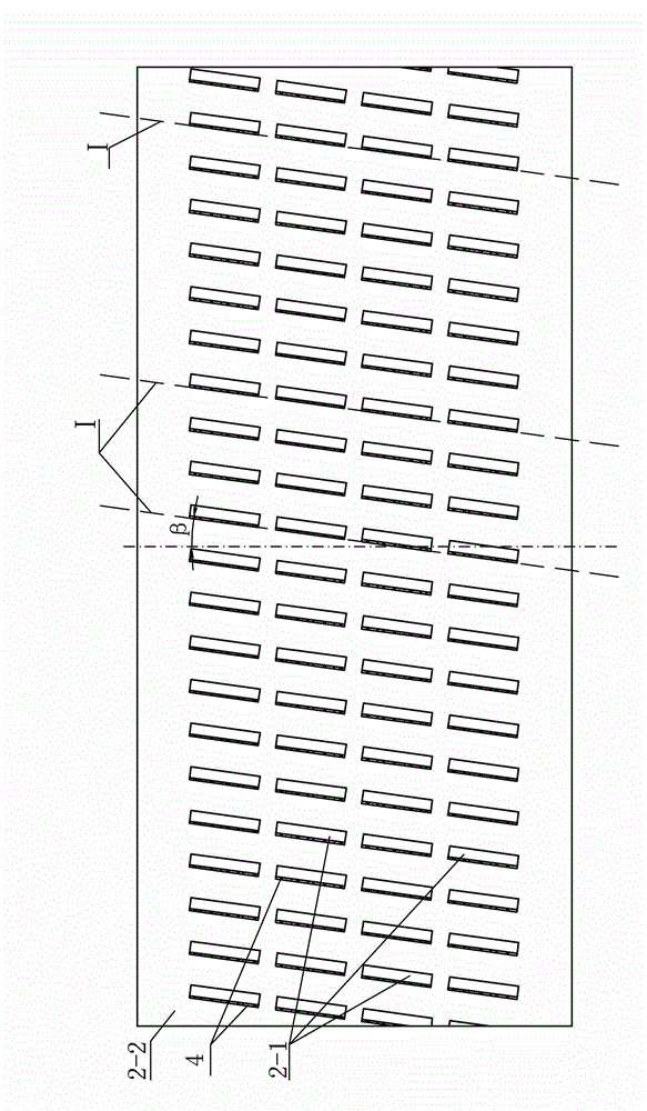
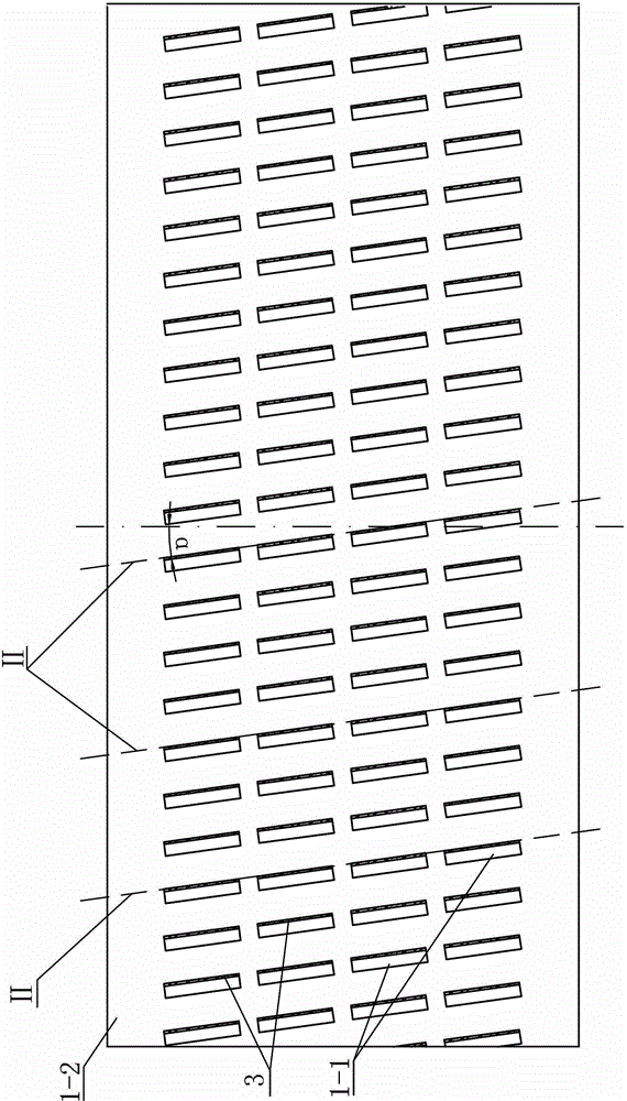
[0009] Specific implementation mode two: combination figure 2 and image 3 This embodiment will be described. The deployed inner blades 4 and outer blades 3 in this embodiment are all rectangular blades. In this way, the inner blade 4 and the outer blade 3 are arranged in cooperation to cut the large-grained dirt and sundries in the water, and break them into small-sized dirt, so that they can enter heat exchange equipment, heat pump units, refrigeration units and other equipment to meet The system is not required to be blocked and improves the treatment effect. Others are the same as in the first embodiment.

specific Embodiment approach 3

[0010] Specific implementation mode three: combination Figure 5 This embodiment will be described. The deployed inner blades 4 and outer blades 3 in this embodiment are all wedge-shaped blades. In this way, the inner blade 4 and the outer blade 3 are arranged in cooperation to cut the large-grained dirt and sundries in the water, and break them into small-sized dirt, so that they can enter heat exchange equipment, heat pump units, refrigeration units and other equipment to meet The system is not required to be blocked and improves the treatment effect. Others are the same as in the first embodiment.


PUM


Abstract

The invention discloses a crushing type blockage prevention device which relates to a blockage prevention device for a sewage heat exchange system and aims to solve the problems of incomplete filtration, miscellaneous clearing operation, big temperature difference loss of the water source and high operating cost in the prior art in the process of processing big-grain sundries contained in the sewage which enters the equipment such as heat exchange equipment. The crushing type blockage prevention device comprises a fixed outer cylinder, a rotary inner cylinder, a shell barrel, a driving device, a plurality of inner blades and equal number of outer blades. The rotary inner cylinder and the fixed outer cylinder are respectively arranged inside the shell barrel; the fixed outer cylinder is sleeved outside the rotary inner cylinder; the driving device is arranged on the upper end face of the shell barrel; the inner blades are distributed on the outer circumferential side face of the rotary inner cylinder; the outer blades which are equal in number with the inner blades and correspond with the inner blades one by one are distributed on the inner circumferential side face of the fixed cylinder; and the rotation direction of each inner blade which takes the shape of a right-handed spiral cylindrical plane is opposite to the rotation direction of the corresponding outer blade. The crushing type blockage prevention device is used for processing the big-grain sundries contained in the sewage which enters the heat exchange system.

Description

technical field [0001] The invention relates to an anti-clogging device for a sewage heat exchange system, in particular to a device for crushing and treating raw sewage entering heat exchange equipment and other equipment, and large particles of dirt in surface water sources. Background technique [0002] In industrial or energy systems, especially in energy systems that use urban raw sewage and surface water sources (river water, river water, lake water, sea water, etc.) Treatment will lead to blockage of heat exchange equipment, and even damage to important equipment such as heat pump units, which will affect the effective operation of the system. Anti-clogging treatment is carried out on the sewage before entering the heat exchange equipment. The common equipment has an anti-blocking machine (for example: the Chinese patent number is ZL200410043654.9, and the invention patent with a publication date of March 16, 2005 provides a kind of roller grid. The urban sewage hydr...

Claims


Application Information

Patent Timeline
Patent Type & Authority Applications(China)
IPC IPC(8): B02C18/08B02C18/16B02C18/18
Inventor 张承虎廖晋林春光
Owner HARBIN INST OF TECH
Why Eureka
Try Eureka