High-speed transverse-swing feeding conveying belt feeding shoe magnet automatic chamfering grinding machine

A conveyor belt and swaying technology, which is applied in the field of tile-shaped magnet automatic chamfering grinders, can solve the problems of stability (poor synchronization, slow feeding speed, product or equipment damage, etc.), achieve stable and reliable work, improve production efficiency, and system good stability effect

Active Publication Date: 2013-01-16
宜宾汇思磁材设备有限公司
View PDF11 Cites 6 Cited by
  • Summary
  • Abstract
  • Description
  • Claims
  • Application Information

AI Technical Summary

Problems solved by technology

[0003] For magnetic tile chamfering processing technology (first, second, third), in addition to processing quality, its processing efficiency is also a very important economic index. The speed is basically the same. The speed and reliability of feeding are the key to determining the entire processing speed. The main problem at this stage is that the feeding speed is slow or the stability (poor synchronization). The continuous linear motion of the conveyor belt input must be converted into the intermittent linear motion of the jacking material. During the jacking process, the materials are discharged sequentially to form a material belt. The pushing device pushes the entire material belt to move at the end. It is necessary to add new materials into the station to ensure the continuity of processing. This supplementary action is a difficult problem in this industry. First, the replenishment cannot affect the normal operation of the grinding process. Secondly, when the tile magnet is input from the conveyor belt Continuous linear motion must be converted into intermittent linear motion of jacking material. In the case of high-speed operation, the synchronization of feeding and jacking mechanical actions requires high precision. A slight error will lead to product or equipment damage, so , the structure of feeding material has a decisive effect on the processing speed of the whole machine

Method used


Image

  • High-speed transverse-swing feeding conveying belt feeding shoe magnet automatic chamfering grinding machine
  • High-speed transverse-swing feeding conveying belt feeding shoe magnet automatic chamfering grinding machine
  • High-speed transverse-swing feeding conveying belt feeding shoe magnet automatic chamfering grinding machine

Examples


Embodiment 1

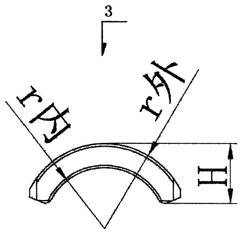
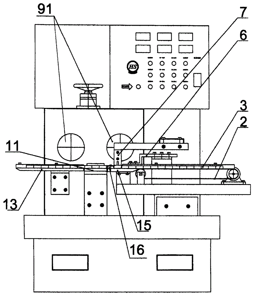
[0024] exist image 3 and Figure 5 Middle: The magnetic tile 3 from the pre-processing equipment is sent to the conveyor belt 2, and the magnetic tile 3 is transferred to the transition plate 15 under the drive of the conveyor belt 2 and continues to move to the left. The magnetic tile 3 is received by the tail of the transition plate 15 The magnetic tile limit block 16 is limited and stops moving, and the shifting block 7 performs periodic yaw motion to make the magnetic tile 3 swing inward to the feeding position (at this time, the push rod 6 is in the retreat gap), when the magnetic tile 3 is in place, the push rod 6 is just in the forward state, and the magnetic tile 3 is pushed to the left to move the magnetic tile 3 to the chamfering tooling 11, and the chamfering tooling 11 moves up and down periodically, and the magnetic tile 3 on it is raised to At the proper position, let the rotating grinding wheel 91 chamfer the outer arc end surface of the magnetic tile 3 (simil...


PUM


Abstract

A high-speed transverse-swing feeding conveying belt feeding shoe magnet automatic chamfering grinding machine comprises an electrical appliance control system, a power device and an abrasive wheel (91), and is characterized by further comprising a transverse-swing assembly, a push rod assembly and a lifting assembly, wherein the transverse-swing assembly, the push rod assembly and the lifting assembly are driven by the power device. The automatic chamfering grinding machine has the advantages that a transverse-swing cam, a push rod cam and a fixture lifting cam move coaxially and synchronously to enable high synchronicity of various independent mechanical movements, and strict synchronization in X-axial, Y-axial and Z-axial linear movement of the magnetic shoe is realized by three rotary cams, one linear cam and four linear movement pairs (a fixture carriage linear movement pair, a push rod carriage linear movement pair, a vertical transition carriage linear movement pair and a swing rod carriage linear pair), and accordingly stable and reliable operation under the high-speed condition can be realized, and the chamfering speed of the automatic chamfering grinding machine is higher than that of the prior art.

Description

technical field [0001] The invention relates to an automatic chamfering grinding machine for tile-shaped magnets fed by a horizontal feeding conveyor belt. It can be used in a fully automatic tile-shaped magnet grinding line. Background technique [0002] When the tile-shaped magnet is grinding the inner and outer arc surfaces, it is often necessary to chamfer the inner and outer arc end faces of the tile-shaped magnet to ensure the normal grinding of the inner and outer arc surfaces. At present, there are four kinds of technologies normally used in production: the existing first technology uses manual grinding to chamfer the inner and outer arc end faces of tile-shaped magnets, and the processing equipment is ordinary grinders replaced with upper planes or arcs. The diamond grinding wheel on the surface is chamfered by the operator holding a magnetic tile on the diamond grinding wheel. The chamfering is labor-intensive, and the accuracy and efficiency of the chamfering dep...

Claims


Application Information

Patent Timeline
Patent Type & Authority Applications(China)
IPC IPC(8): B24B9/06B24B47/00
Inventor 廖敌江曾宇张文彬袁小中
Owner 宜宾汇思磁材设备有限公司
Why Eureka
Try Eureka