
Method and device for welding PTFE (Polytetrafluoroethylene) plates

A welding method and PTFE technology are applied in the field of PTFE plate welding and installation, which can solve the problems of unavailability and achieve the effect of smooth welding seam.

Active Publication Date: 2013-01-16
NANJING COMPTECH COMPOSITES CORP
View PDF6 Cites 9 Cited by
  • Summary
  • Abstract
  • Description
  • Claims
  • Application Information

AI Technical Summary

Problems solved by technology

Can the prior art have why there is no report about PTFE plate butt welding? It may be that after repeated tests, it is still impossible to obtain welds with excellent physical and mechanical properties.

Method used


Image

  • Method and device for welding PTFE (Polytetrafluoroethylene) plates
  • Method and device for welding PTFE (Polytetrafluoroethylene) plates
  • Method and device for welding PTFE (Polytetrafluoroethylene) plates

Examples


Embodiment Construction

[0029] 1. Selection of raw materials

[0030] PTFE plates made of PTFE M-111, PTFE TFM1700, PTFE TFM1705, and PTFE TFM1600 were selected, and welding tests were performed on PTFE plates of the same material.

[0031] 2. Welding device.

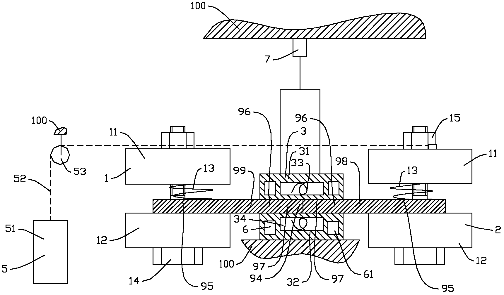
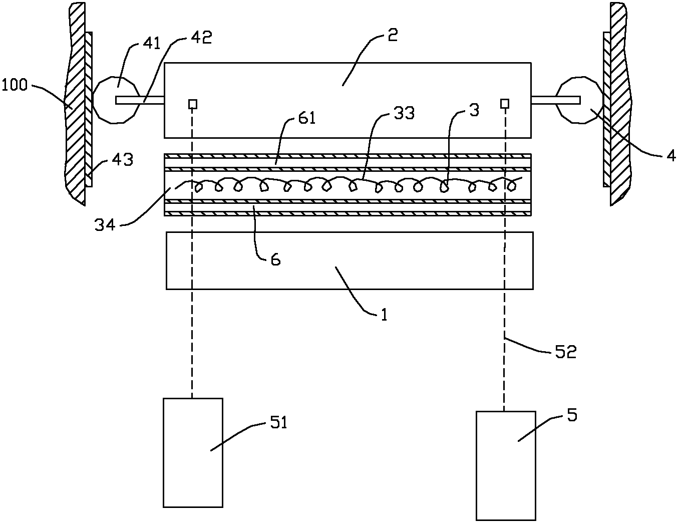
[0032] see figure 1 , 2 The shown PTFE plate welding device includes a frame (100), a fixed plate device (fixing device) 1, a moving plate device (clamping device) 2, a heating device 3, a guiding device 4, a pressurizing device 5, and a cooling device 6 , Oil cylinder (moving device) 7 and so on.

[0033] The fixed plate device 1 has the same structure as the moving plate device (clamping device) 2, and both include an upper pressing plate 11, a lower pressing plate 12, a plurality of compression springs 13, bolts 14, nuts 15 cooperating with the bolts 14, and the like. The compression spring 13 is disposed on the lower surface of the upper pressing plate 11 opposite to the lower pressing plate 12 . Both sides of upper pressing plate 11,...


PUM


Abstract

The invention provides a method and a device for welding PTFE plates. The weld strength and the elongation at break of the welded PTFE plates are not less than 80% of the physical mechanical property of an original plate. The method comprises the following steps: two PTFE plates are in butt joint with each other, and butt-joint areas are heated so as to be melted, then are cooled, and are pressed when being heated, and melts in heating areas can freely flow in the direction vertical to butt-joint seams and parallel to the PTFE plates under the condition of bearing pressure. The device comprises a fixing device used for fixing one PTFE plate, a heating device used for heating the butt-joint areas, a clamping device used for clamping the other PTFE plate, and a pressing device including ropes and pulleys; the ropes are used for hanging balance weights, and are connected with the clamping device through the pulleys; and the balance weights enable the clamped PTFE plate to tightly press the other fixed one in the direction vertical to the butt-joint seams and parallel to the PTFE plates.

Description

technical field [0001] The invention relates to a welding method and device for PTFE plates. Background technique [0002] With the advancement of world industrial technology, especially the rapid development of industries such as aerospace, electronic semiconductors, chemical chemicals, environmental protection engineering, and fluid machinery, these industrial fields are increasingly inseparable from anti-corrosion materials. Nowadays, various advanced anti-corrosion materials are constantly being introduced. Among them, polytetrafluoroethylene (PTFE) has attracted more and more attention due to its excellent chemical stability, high temperature resistance, corrosion resistance, non-stickiness, and excellent lubricating properties. As a special anti-corrosion material, PTFE has been accepted by many industrial fields. [0003] Due to the non-stickiness of PTFE, the bonding between PTFE and PTFE has not been really solved. People have used many methods to try to bond PTFE ...

Claims


Application Information

Patent Timeline
Patent Type & Authority Applications(China)
IPC IPC(8): B29C65/02
Inventor 杨文光张荫谷陈朝曦孙克原陈佩民
Owner NANJING COMPTECH COMPOSITES CORP
Learn More