Vehicle power intelligent management system and method

A management system, power processing technology, applied in circuits or fluid pipelines, vehicle components, transportation and packaging, etc., can solve difficult to adapt to the automotive environment and high current control, engine start control monitoring and protection, intelligent relay coordination It is difficult to control and other problems to achieve the effect of improving electromagnetic anti-interference ability, flexible control, reliability and life expectancy.

Active Publication Date: 2015-12-09
汉纳森(厦门)数据股份有限公司
View PDF5 Cites 0 Cited by
  • Summary
  • Abstract
  • Description
  • Claims
  • Application Information

AI Technical Summary

Problems solved by technology

However, in this patent, multiple relays are mainly used to detect the current of each power supply line, and the circuit is complex; and the coordination of multiple smart relays is difficult to control, which greatly affects the stability of the entire system; in addition, the The patent does not monitor and protect the start control, neutral and emergency start of the engine, which still has great potential safety hazards
Due to the relatively low reliability of relays in the case of high-current control, the self-recovery fuse is sensitive to temperature, and it is difficult to adapt to the automotive environment and high-current control; especially for vehicle power control, its safety and reliability cannot be guaranteed.

Method used


Image

  • Vehicle power intelligent management system and method
  • Vehicle power intelligent management system and method
  • Vehicle power intelligent management system and method

Examples


Embodiment Construction

[0033] The present invention will be further described in conjunction with the accompanying drawings and specific embodiments.

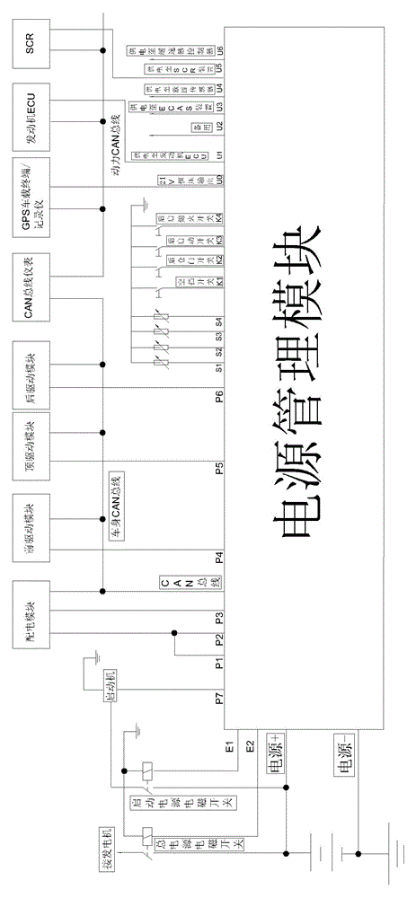
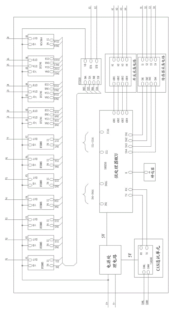
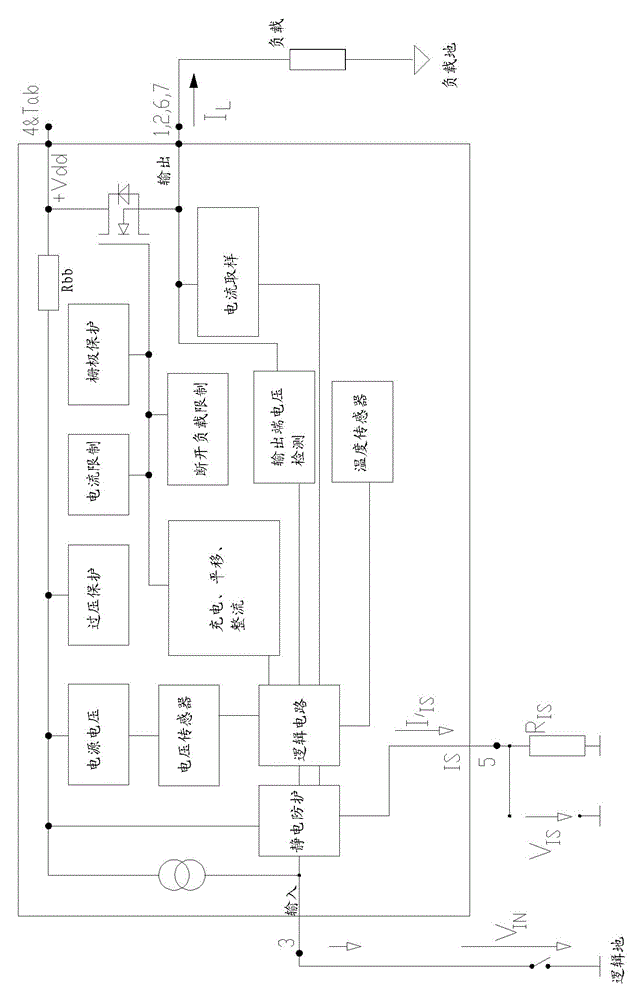
[0034] As a specific embodiment, the intelligent power supply management system of the present invention, such as figure 1 with figure 2 As shown, it includes a microprocessor MCU, a power processing circuit, several intelligent power controllable circuits (realized by intelligent power switches, three types of intelligent power switches are used in this embodiment: BTS50085, BTS740 and BTS5210), a A temperature monitoring unit (realized through a sensor acquisition circuit) and a CAN communication unit.

[0035] The present invention mainly provides power supply and management for each ECU unit externally connected to the vehicle. The power supply input end (that is, the power supply end of the power processing circuit) is connected to the battery and generator power supply of the vehicle, and the power output end (that is, each intelligent power ...


PUM


Abstract

The invention relates to the technical field of automotive electronic control. An intelligent management system of an automobile power supply comprises an MCU (Microprocessor), a power supply processing circuit, a plurality of intelligent power controlled circuits, a temperature monitoring unit and a CAN (Controller Area Network) communication unit, wherein an input end of the power supply processing circuit is connected to a storage battery and an engine power supply; an output end of the power supply processing circuit is connected to the MCU; input ends of the intelligent power controlled circuits are connected to the storage battery, the engine power supply and the MCU; output ends of the intelligent power controlled circuits are connected to a power supply end of an automobile externally connected ECU (Electronic Control Unit); the circuits are used for detecting current and voltage of the storage battery and the engine power supply, simultaneously receiving a control signal of the MCU, and adjusting power output according to the control signal so as to output a plurality of paths of controlled output and constant-voltage output; the temperature monitoring unit is arranged on heating areas of a storage battery bin and an engine bin; an output end of the temperature monitoring unit is connected to the MCU; and a signal end of the CAN communication unit is connected with the automobile externally connected ECU and the MCU. The intelligent management system of the automobile power supply is applicable to automobiles applying the CAN bus technology.

Description

technical field [0001] The invention relates to the technical field of automotive electronic control, in particular to an intelligent management system and method for a vehicle power supply, which is suitable for vehicles applying CAN bus technology. Background technique [0002] At present, with the development of automotive electronic systems, CAN bus (ControllerAreaNetwork-BUS, controller area network bus) technology has been widely used in passenger cars. The use of CAN bus distributed modular control makes the wiring harness on the car simple, and the bus on the car The number of ECU (Electronic Control Unit, electronic control unit) units is increasing, and each ECU unit needs a stable power supply, and also needs to have protection functions, such as over-current, over-voltage and short-circuit protection. [0003] Due to the increase in the number of ECU units, the power supply conditions of each unit are different: for example, some ECU units need to delay power off...

Claims


Application Information

Patent Timeline
Patent Type & Authority Patents(China)
IPC IPC(8): B60R16/02
Inventor 李建红
Owner 汉纳森(厦门)数据股份有限公司
Why Eureka
Try Eureka