
Airship tail vectored thrust device

A vector thrust and thrust device technology, which is applied in aircraft, rigid spacecraft, transportation and packaging, etc., can solve the problems of long control arm of the empennage, difficulty in overcoming airship head-up/down moment, and difficulty in attitude adjustment, so as to increase flight Speed, improve environmental adaptability, increase the effect of control torque

Active Publication Date: 2013-01-16
湖南航天远望科技有限公司
View PDF9 Cites 8 Cited by
  • Summary
  • Abstract
  • Description
  • Claims
  • Application Information

AI Technical Summary

Problems solved by technology

Relying on the deflection of the empennage rudder surface to realize the attitude adjustment of the airship mainly has two problems: one is that as the volume of the airship gradually increases, the length of the airship capsule increases, and the installation position of the empennage on the airship (generally, the leading edge of the empennage root is at a distance from the capsule head). The lower part is the position of 75% of the length of the hull) the farther away from the center of mass of the airship, the longer the control arm of the empennage. Under the action of wind load, it is difficult for the empennage rudder surface to overcome the nose-up / down moment of the airship in a short time, so as to realize Attitude adjustment; the second is that as the flying height of the airship gradually increases (currently, the flying height target of airships developed by various countries is about 20km), the wind field in the working environment of the airship changes drastically, and the maximum wind speed reaches the order of 120m / s when passing through the torrent , and during the level flight at a height of 20km, the wind speed is generally below 10m / s. Such a large difference in the wind field will bring difficulties to the design of the empennage structure and the adjustment of the attitude by the effect of the wind field.

Method used


Image

  • Airship tail vectored thrust device

Examples


Embodiment 1

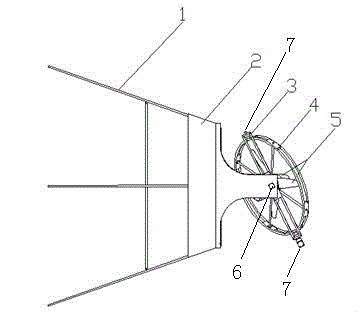
[0012] see figure 1 , the airship tail vector thrust device includes a tail cone 1 with a two-degree-of-freedom turntable base 2 at the rear end; the two-degree-of-freedom turntable base 2 is connected to the turntable controller; the Z-axis rotating body 3 passes through the A screw shaft 6 at both ends Installed on the two-degree-of-freedom turntable base 2, the Z-axis rotating body 3 can deflect ±90° in the vertical plane around the A helical axis 6; the Y-axis rotating body 4 is installed on the Z-axis rotating body 3 through the B helical shaft 7 at both ends Above, the Y-axis rotating body 4 can deflect ±90° in the horizontal plane around the B screw axis 7; the Y-axis rotating body 4 is equipped with a thrust device 5; the thrust device 5 is connected to the thrust device controller.

[0013] Wherein, the tail cone 1 is a circular platform structure, the front end of the tail cone 1 is connected to the tail of the airship capsule through a buckle and a tension wire, and...


PUM


Abstract

The invention discloses an airship tail vectored thrust device which mainly comprises a tail cone, a two-degree-of-freedom rotary table base, a Z-axis rotating body, a Y-axis rotating body and thrust devices. When the airship tail vectored thrust device is operated, deflection of the Z-axis rotating body and the Y-axis rotating body drives the thrust devices to enable the same to rotate tipsily in an airship body plane and a vertical plane within the range of + / -90 degrees, and a certain vectored thrust is generated, so that pitching and yaw attitude adjustment and auxiliary acceleration of an airship are achieved. By the aid of the airship tail vectored thrust device, response speed of airship attitude (pitching and yaw) adjustment is remarkably increased, control torque is increased, flying speed is increased in an assisted manner, and environmental adaptability of the airship is enhanced.

Description

technical field [0001] The technology relates to a tail vector thrust device of an airship, which is used for pitch and yaw attitude adjustment during the flight of the airship, and can assist in increasing the flight speed of the airship, belonging to the field of aerostat control. Background technique [0002] Existing airships mainly rely on the deflection of the tail rudder surface (skin skeleton type or inflatable membrane type) to realize the pitch and yaw control of the airship, thereby realizing the turning, climbing, and descending actions of the airship. The deflection effect of the empennage rudder surface (skin skeleton type or inflatable membrane type) is limited by the wind load, and the deflection range is generally within ±30°. Relying on the deflection of the empennage rudder surface to realize the attitude adjustment of the airship mainly has two problems: one is that as the volume of the airship gradually increases, the length of the airship capsule increa...

Claims


Application Information

Patent Timeline
IPC IPC(8): B64B1/00B64B1/24
Inventor 罗义平侯远波李和飞蹇洁
Owner 湖南航天远望科技有限公司
Learn More