Sludge drying chamber
A sludge drying and sludge technology, applied in the direction of dewatering/drying/concentrating sludge treatment, etc., can solve the problems of inefficient drying method, the inability of working air to achieve the purpose of drying, energy waste, etc., and achieve the goal of improving drying efficiency. Effect
- Summary
- Abstract
- Description
- Claims
- Application Information
AI Technical Summary
Problems solved by technology
Method used
Image

Examples
Embodiment 1
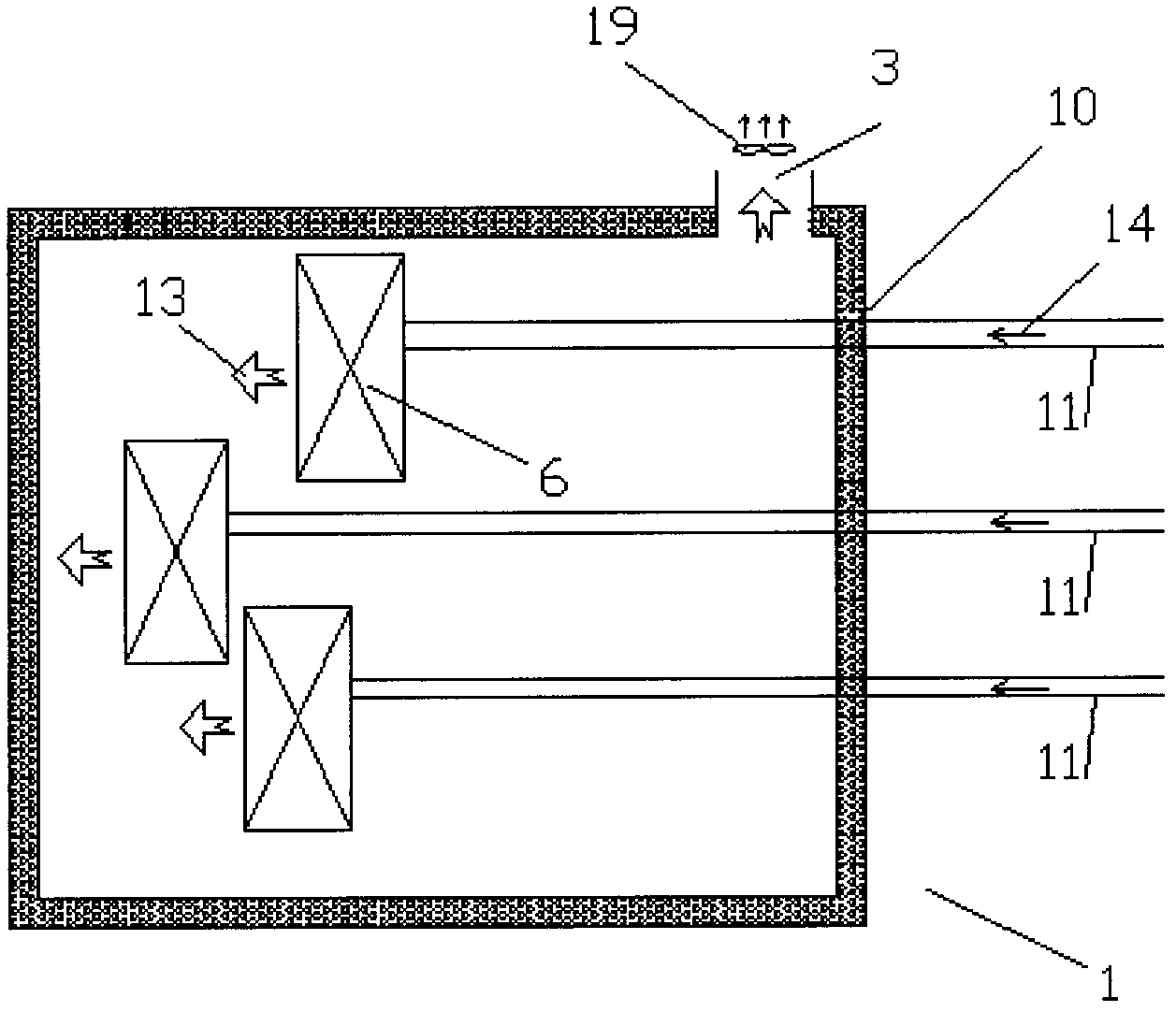
[0027] Such as figure 1 As shown, the sludge drying chamber 1 includes a plurality of working medium air inlets 10, a plurality of working medium air introduction air ducts 11, a sludge dryer 6, and a hot and humid air outlet 3, wherein the working medium air flows along the working medium air The flow direction 14 flows, enters the sludge drying chamber 1 through the air inlet 10 of the working medium, and heats and dries the sludge in the sludge dryer 6, and the hot and humid air formed leaves the sludge dryer 6 according to the hot and humid air flow direction 13, and The hot and humid air is exhausted from the sludge drying chamber 1 through the exhaust outlet 3; the temperature of the working medium air in the air passage 11 of the three working medium air is different, and the sludge in one of the sludge dryers is heated. That is, the sludge drying chamber 1 includes at least two or more than two working fluid air inlets, and the temperature of the working fluid air at a...
Embodiment 2
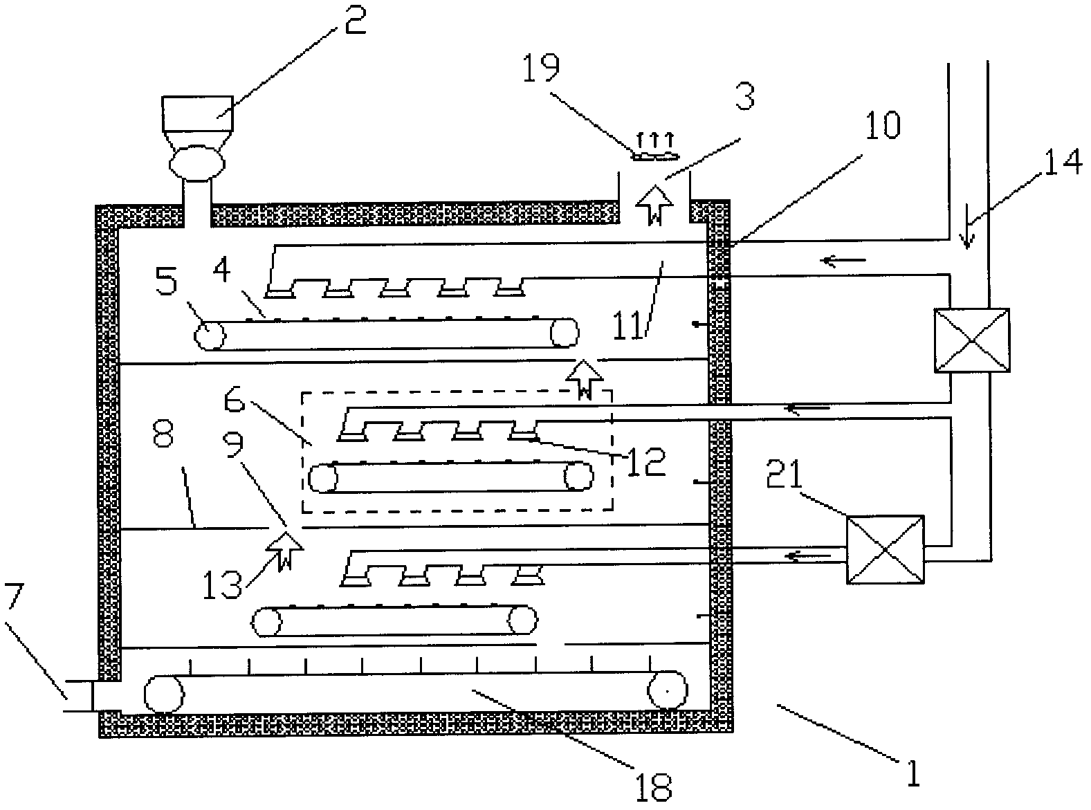
[0033] Such as figure 2 As shown, the difference between this embodiment and Embodiment 1 is that, specifically, the sludge dryer 6 used in this embodiment includes a conveyor belt 5 and a tuyere 12 that blows air to the conveyor belt, and the working medium air is blown to the sludge 4 through the tuyere 12. Above, after the working medium air heats and dries the sludge 4, hot and humid air is formed, and finally the hot and humid air flows to the main exhaust outlet 3 in the direction indicated by the hot and humid air flow direction 13, and is discharged from the sludge drying chamber 1 through the main exhaust fan 19. The wet sludge enters the sludge drying chamber 1, and the process of transportation, heating and drying in the sludge drying chamber has been described in Embodiment 1 and will not be repeated here.
[0034] In addition, in this embodiment, different working medium air temperatures are provided by a heat exchanger 21 on the air duct 11 below which requires ...
Embodiment 3
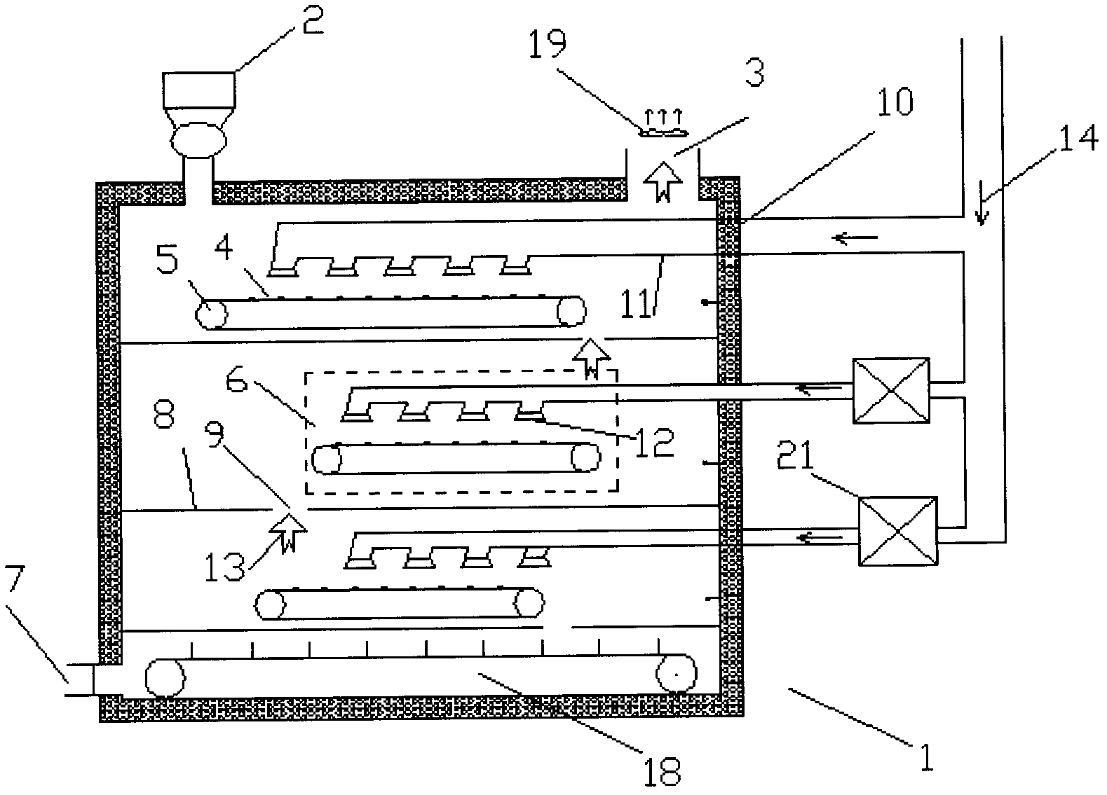
[0041] Such as image 3 As shown, the difference between the present embodiment and the second embodiment is that the heating form of the working medium air is that the middle air duct and the lower air duct adopt their own heat exchangers 21, that is, the working air in the middle air duct and the lower air duct. The temperature of the quality air is determined by the requirements of its process. Such as Figure 6 Shown is a schematic diagram of the heat required by different humidity in the sludge drying process. The abscissa is the sludge humidity W, and the coordinate value is the ratio of the actual water content to the total water content (100%); the ordinate is the energy Q required to dry the sludge , the unit is kilowatts per hour, this kind of sludge in the case of intermediate humidity, specifically when the moisture content is 35-60%, because the sludge particles and water form a similar colloid, so the heat required for drying will be higher than that of the slud...
PUM
 Abstract
Description
Claims
Application Information
 - R&D
- Intellectual Property
- Life Sciences
- Materials
- Tech Scout
- Unparalleled Data Quality
- Higher Quality Content
- 60% Fewer Hallucinations
Browse by: Latest US Patents, China's latest patents, Technical Efficacy Thesaurus, Application Domain, Technology Topic, Popular Technical Reports.
© 2025 PatSnap. All rights reserved.Legal|Privacy policy|Modern Slavery Act Transparency Statement|Sitemap|About US| Contact US: help@patsnap.com