Oil injection control system for engine

A control system and engine technology, applied in the direction of engine control, combustion engine, fuel injection control, etc., can solve problems such as difficulty in engine starting, failure, and difficulty in starting a new car for the first time, so as to avoid the problem of starting failure, improve the impact, and solve the problem. Difficult to start effect for the first time

Active Publication Date: 2013-01-16
UNITED AUTOMOTIVE ELECTRONICS SYST
View PDF4 Cites 10 Cited by
  • Summary
  • Abstract
  • Description
  • Claims
  • Application Information

AI Technical Summary

Problems solved by technology

With the existing engine fuel injection control method, when the engine is started next time, this part of the air in the high-pressure fuel rail will be compressed to form air resistance or a plurality of tiny air bubbles, so that the actual amount of f

Method used


Image

  • Oil injection control system for engine
  • Oil injection control system for engine
  • Oil injection control system for engine

Examples


Embodiment 1

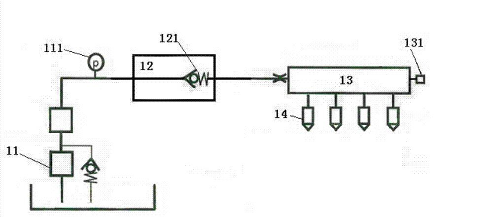
[0043] Engine fuel injection control system, including a fuel injection control module;

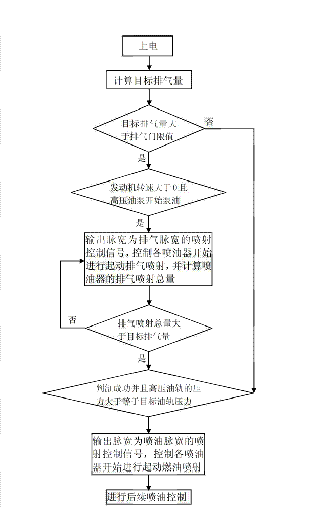
[0044] The workflow of the fuel injection control module, such as image 3 As shown, including the following steps:

[0045] One power up;

[0046] 2. Calculate the target exhaust volume;

[0047] 3. If the target exhaust volume is greater than an exhaust threshold, proceed to step 4, otherwise proceed to step 5;

[0048] four. If the engine speed is greater than 0 and the high-pressure oil pump starts pumping oil, it outputs an injection control signal whose pulse width is the exhaust pulse width, controls each injector to start exhaust gas injection, and calculates the total amount of exhaust gas injection of the injector;

[0049] 5. If the total exhaust gas injection volume of the injector is greater than the target exhaust volume, proceed to step 6; otherwise, proceed to step 4;

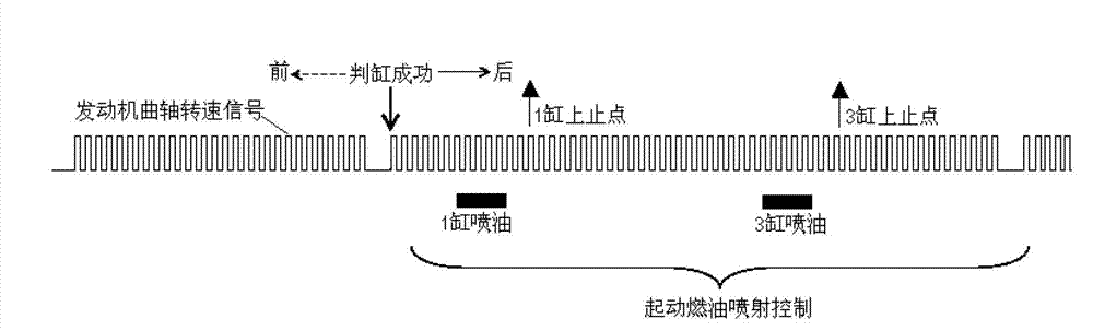
[0050] 6. If the cylinder is judged successfully and the pressure of the high-pressure fuel rail is greater than or...

Embodiment 2

[0054] Based on the first embodiment, the engine fuel injection control system further includes a memory;

[0055] The memory stores the calibrated exhaust threshold value, exhaust pulse width, fuel injection pulse width, and target fuel rail pressure;

[0056] Exhaust threshold and target fuel rail pressure can be calibrated based on experimental and empirical values;

[0057] The exhaust pulse width is calibrated according to the determined minimum fuel injection pulse width Timn;

[0058] The fuel injection pulse width is calibrated according to experimental and empirical values, and the fuel injection pulse width is greater than the determined minimum fuel injection pulse width Timn;

[0059] The minimum fuel injection pulse width refers to the minimum pulse width for the injector to achieve effective fuel injection. The size of the minimum fuel injection pulse width Timn mainly depends on the electromagnetic force of the solenoid valve to lift the injector needle valve, the fuel ra...

Embodiment 3

[0067] Based on the second embodiment, the memory also stores a calibrated exhaust interval, and the calibrated exhaust interval is greater than or equal to the minimum fuel injection pulse width Timn;

[0068] The fuel injection control module outputs an exhaust injection control signal with a pulse width of the exhaust pulse width, and when controlling each injector to start exhaust injection, the time interval between two consecutive injections of the same injector is equal to the calibrated Exhaust interval.


PUM


Abstract

The invention discloses an oil injection control system for an engine. The system comprises the steps of: after electrification, first, calculating a target displacement of a high pressure oil track; when the target displacement is greater than the displacement threshold value, triggering to start displacement and injection control, or, judging the cylinder; after cylinder judgment is successful and the high pressure oil track meets the target oil track pressure, controlling normally to start fuel injection; under displacement injection control mode, controlling displacement injection with narrower displacement pulse width injection control signals when engine rotating speed signals exist and high pressure oil pump starts pumping oil; if, the displacement injection total amount is greater than the target displacement amount, and the cylinder judgment is successful and the high pressure oil track meets the target oil track pressure, controlling normally to start fuel injection. The oil injection control system for the engine can effectively improve the influence of residual air in the high pressure oil track to actual starting oil injection amount, improves the precision of fuel injection in the starting stage, and avoids start failure.

Description

Technical field [0001] The invention relates to automobile technology, in particular to an engine fuel injection control system. Background technique [0002] The structure of the electronically controlled engine high-pressure injection fuel system is as figure 1 As shown, the system has two-stage oil pumps, a low-pressure oil pump 11 and a high-pressure oil pump 12. The engine fuel injection control system controls the high-pressure oil pump 12 according to the signal of the high-pressure sensor 131 on the high-pressure oil rail 13 to achieve closed-loop control of the target oil rail pressure; According to fuel rail pressure and engine operating condition information, high-pressure fuel injection control is realized. At the junction of the high-pressure oil pump 12 and the high-pressure oil rail 13, a mechanical one-way valve 121 is provided to maintain a certain residual oil pressure in the high-pressure oil rail 13 under engine shutdown conditions to facilitate the next start...

Claims


Application Information

Patent Timeline
IPC IPC(8): F02D41/38
CPCY02T10/47Y02T10/40
Inventor 于世涛习纲李君
Owner UNITED AUTOMOTIVE ELECTRONICS SYST
Why Eureka
Try Eureka