
Pneumatic actuator for angular travel valve

A pneumatic actuator, angular stroke technology, applied in engine components, valve operation/release devices, valve details, etc., can solve the problems of many fault points, uneven rotation, high manufacturing cost, and achieve low production cost and structure. Simple, long-lasting effects

Inactive Publication Date: 2013-01-16
许波
View PDF3 Cites 9 Cited by
  • Summary
  • Abstract
  • Description
  • Claims
  • Application Information

AI Technical Summary

Problems solved by technology

Therefore, the existing pneumatic quarter-turn actuators have a large body, complex structure, uneven rotation, impact, and high manufacturing cost. At the same time, due to the complex structure, there are many fault points, resulting in a high failure rate.
Especially when the use and installation space are limited, its disassembly is also very difficult. Although those skilled in the art have made some improvements, they have not fundamentally solved the problem of pneumatic angular stroke execution in the prior art. The above-mentioned problems in the organization

Method used


Image

  • Pneumatic actuator for angular travel valve
  • Pneumatic actuator for angular travel valve
  • Pneumatic actuator for angular travel valve

Examples


Embodiment 1

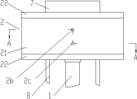
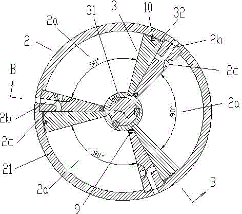
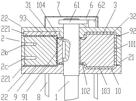
[0022] Example 1 see figure 1 , figure 2 , image 3 , a pneumatic actuator for quarter-turn valves, comprising a quarter-turn valve stem 1, a cylinder block 2, a piston 3, and a reset device for resetting the piston 3, and the cylinder block 2 is formed with mutually independent 3 chambers 2a distributed in a circle, and each chamber 2a communicates with an air intake channel 2b and an exhaust channel 2c for intake and exhaust respectively; the piston 3 consists of a piston sleeve 31 and 3 piston plates 32, the piston sleeve 31 is set on the piston sleeve 31 fixed on the valve stem 1 through a key connection, and the circumference of the piston pieces 32 is evenly distributed on the outside of the piston sleeve 31, and each piston piece 32 is respectively located in a corresponding chamber 2a, and the piston The piece 32 can be driven by compressed air to rotate 0-90° in the chamber 2a; the resetting device is used to make the piston 3 rotate and reset.

[0023] The cyl...

Embodiment 2

[0035] Example 2 see Figure 9 , Figure 10 The valve rod 1 is located outside the cylinder body 2 and is connected with an elastic element 4 for making the piston 3 rotate and reset.

[0036] The elastic element 4 is a coil spring, the inner end of the coil spring is fixed on the valve rod 1, the outer end of the coil spring is fixed on the transparent cover 22 of the cylinder block 2 through the pin shaft 23, and the coil spring is provided with a coil spring Cover 5 is protected.

[0037] The rest of the structure of this embodiment is the same as that of Embodiment 1, and will not be repeated here.


PUM


Abstract

The invention discloses a pneumatic actuator for an angular travel valve. The pneumatic actuator comprises an angular travel valve rod, a cylinder body, a piston and a resetting device for resetting the piston, wherein two to three chambers which are independent from one another and distributed along circumference are formed on the cylinder body, and each chamber is communicated with a gas inlet channel and a gas outlet channel which are respectively used for gas inlet and outlet; the piston is composed of a piston sleeve and two to three piston pieces, and the piston sleeve is sleeved and fixed on the valve rod through a key connecting mode; the circumferences of the piston pieces are uniformly distributed on the outer side of the piston sleeve, the quantity of the piston pieces is the same as that of the chambers, and each piston piece is positioned in the corresponding chamber and can be pushed by compressed air to rotate by 0 to 90 degrees in the chamber; and the resetting device is composed of a coil spring for resetting the piston after rotation. The pneumatic actuator provided by the invention has the beneficial effects of being simple in structure, free from impact, convenient to install and maintain and low in production cost, being capable of rotating stably at a constant speed, having a low failure rate and a long service life, and occupying small area by section.

Description

technical field [0001] The invention relates to a pneumatic actuator for opening and closing control of valves, in particular to a pneumatic actuator for angular stroke valves such as ball valves and butterfly valves, the angular stroke of which is 0-90°. Background technique [0002] Valves are widely used in metallurgy, energy, chemical industry, petroleum, coal gasification and other industries, and ball valves, butterfly valves, globe valves and other valves that make the valve core rotate at a certain angle to adjust or switch the flow capacity of the medium are all operated by electric or pneumatic angle. The stroke actuator is realized. In the prior art, for ball valves, butterfly valves and other valves with an angular stroke of 0 to 90°, the pneumatic angular stroke actuators usually adopt a cylinder or a membrane airbag structure no matter at home or abroad, and the direct movement of the cylinder or membrane airbag The stroke movement is converted into an angular...

Claims


Application Information

Patent Timeline
IPC IPC(8): F16K31/122
Inventor 许波
Owner 许波
Learn More