Method for laying tunnel portal strengthened illuminating system

A lighting system and tunnel entrance technology, applied in the field of tunnel entrance enhanced lighting system layout, can solve problems such as rapid changes in pupil area, traffic accidents, occurrence, etc., and achieve the effects of filtering harmful radiation, softening light, and protecting physical and mental health.

Active Publication Date: 2013-01-16
SHANGHAI TUNNEL ENGINEERING RAILWAY TRANSPORTATION DESIGN INSTITUTE +1
View PDF2 Cites 13 Cited by
  • Summary
  • Abstract
  • Description
  • Claims
  • Application Information

AI Technical Summary

Problems solved by technology

[0003] The direct reason for the sharp change of illumination at the entrance and exit of the tunnel is actually the illumination within the range of 50m from the entrance and exit of the tunnel. The change speed of the driver's pupil area can be used as an evaluation index for driving safety at the entrance and exit of the tunnel, and the sharp change of illumination will cause driving The pupil area of ​​the driver changes rapidly, which further leads to the occurrence of traffic accidents

Method used


Image

  • Method for laying tunnel portal strengthened illuminating system
  • Method for laying tunnel portal strengthened illuminating system
  • Method for laying tunnel portal strengthened illuminating system

Examples


Embodiment

[0018] Embodiment: In this embodiment, a light guide lighting system and lighting technology suitable for the environment is mainly developed for the large exhaust gas and high humidity of automobiles in the tunnel.

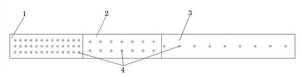
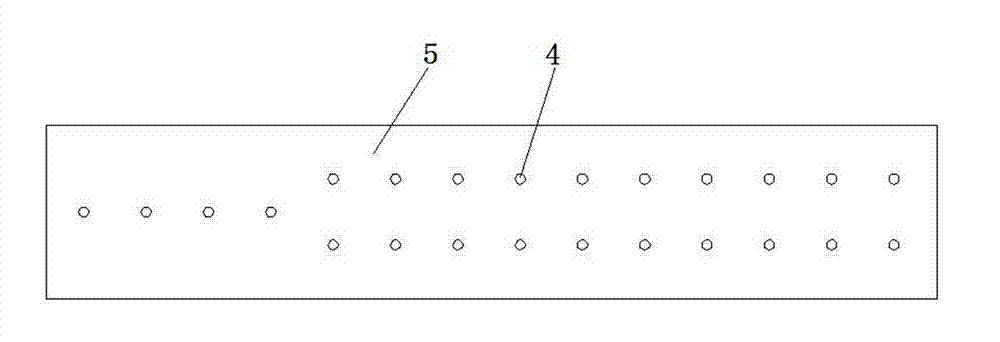
[0019] like figure 1 As shown, the lighting layout of the tunnel entrance section 1 adopts the method from dense to sparse. First, a number of illuminators 4 are arranged at the entrance section 1, so that the tunnel entrance section 1 can initially reduce the illuminance of the road outside the tunnel (the reduction coefficient meets the corresponding tunnel lighting design specifications), and the entrance section 1 is followed by the transition section 2 and the transition section 3. , wherein the arrangement spacing area of ​​the illuminators 4 in the transition section 2 is larger than the arrangement spacing area of ​​the illuminators 4 in the entrance section 1, and the illuminator 4 arrangement spacing area in the transition section 3 is larger than the i...


PUM


Abstract

The invention relates to the field of tunnel engineering, in particular to a method for laying a tunnel portal strengthened illuminating system. The method is characterized in that a plurality of illuminating devices are arranged in an entrance section and an exit section, and the illuminating devices arranged in the entrance section or the exit section are distributed in a thinning mode from a tunnel portal to a distribution area in a tunnel, namely the illumination level is reduced gradually from the tunnel portal to the inside of the tunnel. The method for laying the tunnel portal strengthened illuminating system has the advantages that the laying scheme is acquired by setting up a testing shed in the site to analyze, compare and select data of a plurality of schemes, and light guides are arranged in the entrance section and the exist section of the tunnel by the laying scheme to replace high strength gas-discharge light sources, so that the gentle transition of the illumination levels on road surfaces inside and outside the tunnel is realized, and the zero electric energy loss of tunnel strengthened illumination is realized.

Description

technical field [0001] The invention relates to the field of tunnel engineering, in particular to a method for laying out an enhanced lighting system at a tunnel entrance. Background technique [0002] Current research shows that tunnel entrances and exits are the main road sections that form accident black spots. The sharp change of the illumination at the entrance and exit of the tunnel greatly increases the visual psychophysiological compound of the driver, induces bad driving behavior, and even leads to traffic accidents. However, the current domestic scholars' research on highway tunnels mainly focuses on the current safety design and the theoretical method of driving sight distance, lacking the support of driving tests and lack of tunnel samples. [0003] The direct reason for the sharp change of the illumination at the entrance and exit of the tunnel is actually the lighting condition within the range of 50m from the entrance and exit of the tunnel. The change speed ...

Claims


Application Information

Patent Timeline
Patent Type & Authority Applications(China)
IPC IPC(8): F21S11/00F21V13/12F21V9/06F21W131/101
Inventor 沈蓉季倩倩杨方勤何铁峰蔡岳峰
Owner SHANGHAI TUNNEL ENGINEERING RAILWAY TRANSPORTATION DESIGN INSTITUTE
Why Eureka
Try Eureka