
Thawing device and refrigerator with thawing device

A technology for refrigerators and fixing devices, applied in the field of thawing devices and refrigerators, which can solve the problems of recycling and utilization of cooling capacity of food that cannot be thawed, loss of food nutrition, waste of energy, etc., achieve uniform upper and lower temperature, improve heat transfer efficiency, and enhance flexibility sexual effect

Active Publication Date: 2013-01-16
HENAN XINFEI ELECTRICAL EQUIP
View PDF10 Cites 11 Cited by
  • Summary
  • Abstract
  • Description
  • Claims
  • Application Information

AI Technical Summary

Problems solved by technology

The above two thawing methods will waste space, neither can recycle the cooling capacity of the thawed food itself, and the high temperature thawing will also lead to the loss of food nutrition; in addition, the first thawing method uses an electric heater, so there is additional waste energy
[0004] Compared with metals such as silver, copper, and aluminum, heat pipes can transfer several orders of magnitude more heat per unit weight, and have the advantages of excellent isothermal properties and heat flow direction reversibility. At present, heat pipes are mainly used for heat dissipation and uniformity of electronic devices. Wen, there is no precedent for the introduction of heat pipe technology in the field of domestic refrigeration technology

Method used


Image

  • Thawing device and refrigerator with thawing device
  • Thawing device and refrigerator with thawing device
  • Thawing device and refrigerator with thawing device

Examples


Embodiment Construction

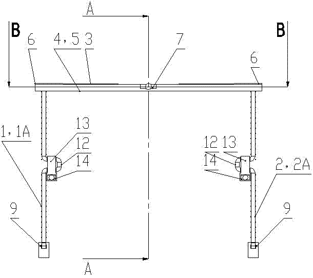
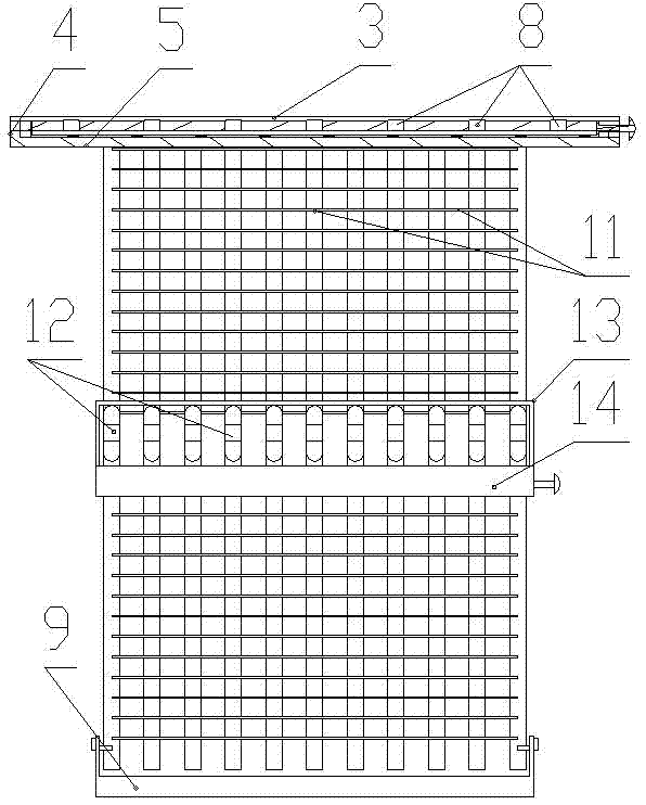
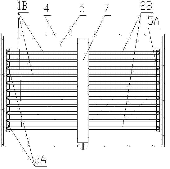
[0029] Such as Figure 1 to Figure 6 As shown, the thawing device of the present invention includes a first heat pipe group 1 and a second heat pipe group 2, the first heat pipe group 1 and the second heat pipe group 2 both include vertical parts, and the vertical part of the first heat pipe group 1 is shown in the figure As shown in 1A, the vertical part of the second heat pipe group 2 is shown in 2A. The tops of the vertical parts 1A and 2A are bent to form a horizontal part, the horizontal part of the first heat pipe group 1 is shown as 1B in the figure, and the horizontal part of the second heat pipe group 2 is shown in the figure as 2B. The transverse parts 1B, 2B of the first heat pipe group 1 and the second heat pipe group 2 are fixed by a fixing device, and the free ends of the transverse parts 1B, 2B of the two heat pipe groups face each other. Wherein, the heat pipe can be a phase-change heat pipe or a non-phase-change heat pipe, and the size of the heat pipe, the i...


PUM


Abstract

The invention discloses a thawing device, which comprises a first heat pipe group and a second heat pipe group, wherein the first heat pipe group and the second heat pipe group comprise vertical parts; the tops of the vertical parts are provided with transverse parts in a bending mode; the transverse parts of the first heat pipe group and the second heat pipe group are fixed by a fixing device, and free ends of the transverse parts of the two heat pipe groups are opposite to each other; the fixing device comprises a fixing frame; the top and bottom of the fixing frame are respectively and fixedly provided with an upper heat transfer storage rack plate and a lower heat transfer storage rack plate; the transverse parts of the first and second heat pipe groups are positioned between the upper and lower heat transfer storage rack plates; and protruding parts, which are matched with a liner slideway of a refrigerator freezer, are extended out of the left and right parts of the fixing frame. The invention also discloses a refrigerator with the thawing device. The refrigerator and the thawing device have the advantages that the refrigerator is convenient to use, the energy is saved, independent thawing space is not required, an electric heater is not required, the condensate water produced during thawing can be automatically collected, when the refrigerator with the thawing device is used, the temperature inside the freezer is uniform and the like.

Description

technical field [0001] The invention relates to the technical field of refrigeration, in particular to a thawing device and a refrigerator provided with the thawing device. Background technique [0002] A refrigerator is a commonly used low-temperature storage household appliance, and generally includes a freezer for freezing food and a refrigerator for freezing food. Usually the temperature of the freezer is maintained at minus 18 degrees Celsius and below, and the temperature of the refrigerator is generally around 5 degrees Celsius. Therefore, the food taken out from the freezer needs to be thawed before cooking. Not only does it take a long time to thaw food, but inappropriate thawing methods can easily cause nutrient loss. [0003] The refrigerator with thawing chamber mainly contains two kinds at present: the first kind is the thawing device proposed in the Chinese patent CN97126440. The second is that the Chinese patent CN02121055.1 proposes to use the waste heat o...

Claims


Application Information

Patent Timeline
Patent Type & Authority Applications(China)
IPC IPC(8): F25D23/00F25D11/02
Inventor 王允宋新洲廉小磊付士健肖建军熊征王蕾蕾王兰敬
Owner HENAN XINFEI ELECTRICAL EQUIP
Learn More