Dynamic wave-front testing device

A test device and wavefront technology, applied in the field of optical testing, can solve problems such as the inability to realize the optical wavefront test of external light source and white light wavefront test, the inability to truly reflect the working wavefront of the lens, and the inability to evaluate the optical system to achieve high precision High, less artificial links, high stability effect

Inactive Publication Date: 2014-05-21
XI'AN INST OF OPTICS & FINE MECHANICS - CHINESE ACAD OF SCI
View PDF5 Cites 0 Cited by
  • Summary
  • Abstract
  • Description
  • Claims
  • Application Information

AI Technical Summary

Problems solved by technology

The dynamic phase-shifting interferometer developed by 4D Company adopts Twyman-Green type, which realizes four-step phase shifting based on the pixel phase template, but a single CCD receives 4 interferograms, and the resolution is reduced by 1 / 2, and is approximated by adjacent pixels. Limited accuracy, and expensive, high cost, poor economy
For optical systems that work in specific wavelength bands, such as the working bands of the Shenguang III host device are 1053nm and 351nm, the optical system cannot be evaluated by using a general interferometer
For wide-band, large-aperture, and long-focus telephoto systems, due to chromatic aberration and other effects, using a single wavelength to evaluate the camera cannot truly reflect the working wavefront of the lens when it is actually used
Optical wavefront testing and white light wavefront testing with external light sources cannot be achieved with traditional interferometers

Method used


Image

  • Dynamic wave-front testing device
  • Dynamic wave-front testing device
  • Dynamic wave-front testing device

Examples


Embodiment Construction

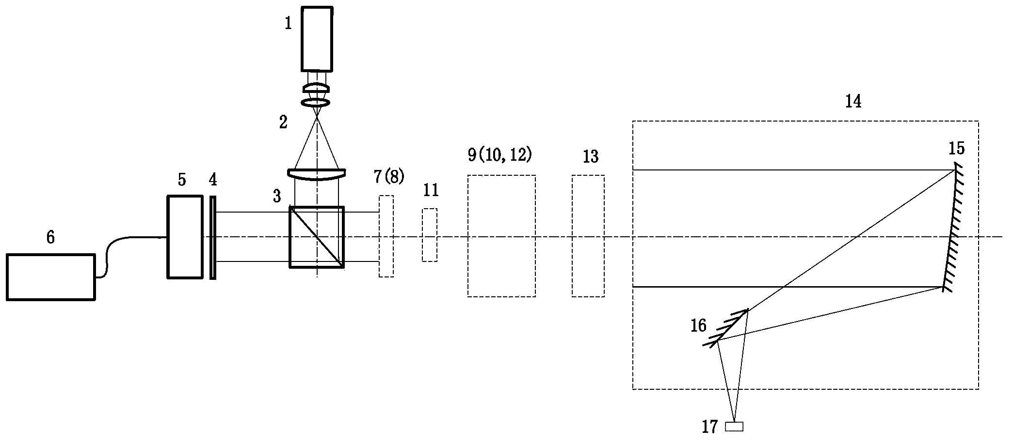
[0018] The invention provides a dynamic wavefront testing device, which comprises an active light source, a passive light source, a beam splitter, a calibration mirror, a standard lens, a microlens array, a CCD detector and a computer; the beam splitter is arranged on the active light source And the incident light path of the passive light source; the beam splitter divides the incident light of the active light source into active reflected light and active transmitted light; the beam splitter divides the incident light of the passive light source into passive transmitted light and passive reflected light; The optical path of the active reflected light or set on the outgoing light path of the passive light source; the calibration mirror and the standard lens are set on the light path between the beam splitter and the optical element to be tested; the microlens array is set on the light path of the passive transmitted light or set on the The active reflected light is transmitted ...


PUM


Abstract

The invention relates to a dynamic wave-front testing device. The dynamic wave-front testing device comprises an active light source, a passive light source, a spectroscope, a calibration mirror, a standard lens, a micro-lens array and a CCD (charge coupled device) detector, wherein the spectroscope is arranged on the incident light paths of the active light source and the passive light source to split the incident light of the active light source into active reflected light and active transmitted light and to split the incident light of the passive light source into passive transmitted light and passive reflected light; the calibration mirror and the standard lens are arranged on the light path between the spectroscope and an optical element to be tested; the micro-lens array is arranged on the light path of the passive transmitted light; and the CCD detector is arranged on the light path of emergent light passing through the micro-lens array. The dynamic wave-front testing device provided by the invention is immune to the external environment, and can ensure the testing accuracy.

Description

technical field [0001] The invention belongs to the technical field of optical testing, and relates to a dynamic wavefront testing device, in particular to a dynamic wavefront testing device capable of dynamic active and passive testing of optical element surface shape or optical system wave aberration. Background technique [0002] With the development of my country's space science and technology and the construction of Shenguang III main equipment, the use of various optical components and optical systems with large aperture and long focal length is increasing day by day. Due to the influence of air flow turbulence and vibration, the static phase-shift interferometer driven by piezoelectric ceramics cannot perform real-time dynamic measurement of the surface shape and wave aberration of the telephoto system. At present, the domestic measurement of the surface shape of large-aperture optical components and the wave aberration of optical systems mainly relies on the dynamic ...

Claims


Application Information

Patent Timeline
Patent Type & Authority Patents(China)
IPC IPC(8): G01J9/00G01B11/24G01M11/02
Inventor 段亚轩陈永权赵建科徐亮李坤田留德
Owner XI'AN INST OF OPTICS & FINE MECHANICS - CHINESE ACAD OF SCI
Why Eureka
Try Eureka