Miniature onboard reverse plug flow cloud droplet sampling device and working method thereof

A technology of sampling device and minicomputer, which is applied in the direction of sampling device, etc., can solve the problems of high purchase cost, large size of aviation atmospheric observation sampler, hindering research development, etc., and achieve the effect of convenient processing, convenient application and wide application

Inactive Publication Date: 2013-01-16
SHANDONG UNIV
View PDF4 Cites 10 Cited by
  • Summary
  • Abstract
  • Description
  • Claims
  • Application Information

AI Technical Summary

Problems solved by technology

[0003] At present, the air pollutant airborne atmospheric observation samplers used are relatively large in size, expensive to purchase, and all of them are imported from abroad, which

Method used


Image

  • Miniature onboard reverse plug flow cloud droplet sampling device and working method thereof
  • Miniature onboard reverse plug flow cloud droplet sampling device and working method thereof
  • Miniature onboard reverse plug flow cloud droplet sampling device and working method thereof

Examples


Embodiment 1

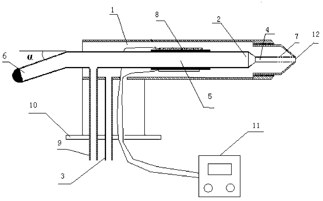
[0026] A small-sized airborne reverse push flow cloud drop sampling device, comprising an air intake chamber 1 and a collection chamber 2, the collection chamber 2 is arranged inside the air intake chamber 1; the front end of the air intake chamber 1 and the sampling chamber of the collection chamber The outer edge of the end is connected, the front end of the air inlet chamber 1 is tapered, and the tail of the air inlet chamber 1 is provided with an air inlet pipe 3; the collection chamber 2 includes a tubular sampling end 4 connected in sequence, a preheating chamber 5 and a tubular capture end 6, the tube wall of the tubular sampling end 4 is provided with a microhole 7, and a heating device 8 is arranged around the outer wall of the preheating cavity 5, and the heating device is a heating rod Thermocouple; an exhaust pipe 9 is arranged at the tail of the preheating cavity 5, and the preheating cavity 5 is a copper tube.

[0027] Described small-sized airborne reverse push ...

Embodiment 2

[0030] A method of collecting cloud droplets utilizing the small-sized airborne reverse push flow cloud droplet sampling device described in embodiment 1, comprising steps as follows:

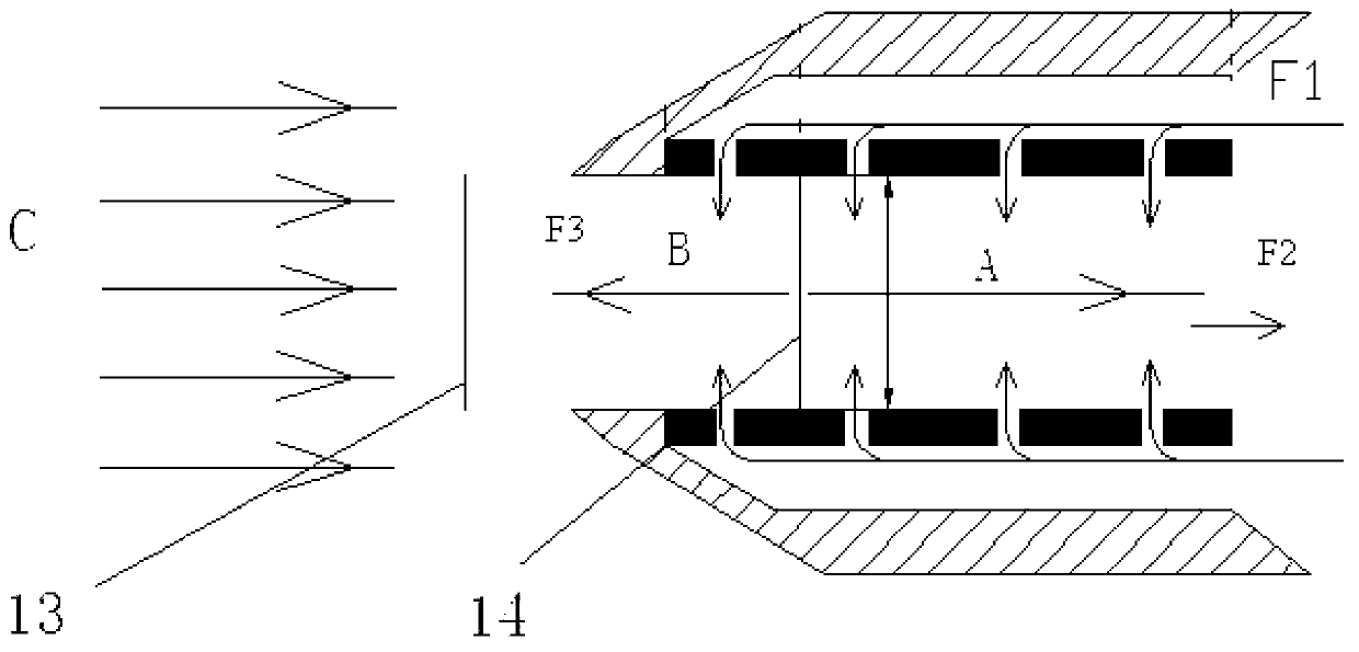
[0031] (1) The sample gas enters the intake chamber 1 along the intake pipe 3, and heats the preheating chamber 5 to 48-52°C;

[0032] (2) The sampling gas in the intake chamber 1 enters the collection chamber 2 along the micropore 7 on the tubular sampling end 4, the flow rate F1 of the sampling gas in the intake pipe 3 is greater than the flow rate F2 of the exhaust pipe, and the When the sampling gas passes through the tubular sampling end 4 with micropores 7, it is divided into two channels of sampling gas: the flow rate F2 and direction of the sampling gas A of one channel are the same as that of the sampling gas in the extraction pipe, and the sampling gas B of the other channel is the same as that of the sampling gas in the extraction tube. The direction is opposite, the flow is F3; the ...

Embodiment 3

[0040] Cloud drop sampling device as described in embodiment 1, its difference is,

[0041] The length of the tubular sampling end 4: 8mm, the diameter of the tubular sampling end: 1.5mm; there are many circles of microholes around the tubular sampling end, the number of microholes in each circle is 6, and the interval between adjacent circles is 1.5 mm. mm; the diameter of the micropore: 10 μm; the diameter of the preheating cavity: 4 mm; the diameter range of the air inlet cavity: 18 mm. The tubular capturing end is at an angle of 25° counterclockwise to the horizontal.

[0042] The particle size range of the aerosol particles or cloud droplets collected by the cloud droplet sampling device described in this embodiment is between 5-10 μm, which meets the experimental requirements for selectively collecting large aerosol particles or cloud droplets.


PUM

PropertyMeasurementUnit
Lengthaaaaaaaaaa
Diameteraaaaaaaaaa
Diameteraaaaaaaaaa

Abstract

The invention relates to a miniature onboard reverse plug flow cloud droplet sampling device, which comprises an air inlet cavity and a collection cavity, wherein the collection cavity is formed in the air inlet cavity; the front end of the air inlet cavity is connected with the outer edge of the sampling end of the collection cavity; an air inlet pipe is arranged on the tail part of the air inlet cavity; the collection cavity comprises the tubular sampling end, a preheating cavity body and a tubular capturing end, which are sequentially connected; a through micropore is formed on the tube wall of the tubular sampling end; a heating device is arranged on the outer wall of the preheating cavity body in a surrounding way; and an extraction pipe is arranged on the tail part of the preheating cavity body. The sampling device can be special for collecting aerosol particles or cloud droplets with large particle sizes. The sampling device and the working method thereof are widely usable, less in investment, convenient to use and practically significant, and the feasibility and practicability of an aviation sampling technology are improved.

Description

technical field [0001] The invention relates to a small-sized airborne reverse push flow cloud drop sampling device and a working method thereof, belonging to the technical field of physical and chemical sampling equipment and analysis of atmospheric clouds. Background technique [0002] With the decline of air quality and the development of aviation technology, researchers at home and abroad have started to study the method of atmospheric sampling on airplanes—aero-sampling technology since the mid-1980s. The application of aerial sampling technology is conducive to understanding the air quality conditions at high altitudes and then studying the causes of air pollution. At present, a large number of studies have shown that aerosol particles emitted by a large number of industrial and urban pollution sources can affect the formation and lifespan of clouds. Due to the limitations of current sampling techniques, most of these problems are speculated through satellite observati...

Claims


Application Information

Patent Timeline
IPC IPC(8): G01N1/22
Inventor 李卫军陈建民刘磊朱超赵立宁刘澎
Owner SHANDONG UNIV
Why Eureka
Try Eureka