Anti-interference system and method based on digital beam forming and space-time zeroing cascade

A technology of digital beam and zero adjustment, applied in the field of satellite navigation, can solve the problems of small amount of calculation, large amount of calculation, small beam width, etc., and achieve the effect of fast and agile

Inactive Publication Date: 2013-01-16
北京北方联星科技有限公司
View PDF3 Cites 54 Cited by
  • Summary
  • Abstract
  • Description
  • Claims
  • Application Information

AI Technical Summary

Problems solved by technology

3. Space-time adaptive (STAP) technology: Compared with pure time domain and frequency domain technology, spatial domain filtering technology has obvious advantages, and is relatively simple to implement and has a small amount of calculation, but there are two shortcomings: ① If the array unit The number is M, and the maximum number of nulls that the array can generate is M-1, which is also the maximum number of interferences that the array can eliminate.
This statement does not rule out the possibility that one null can eliminate two interferences, because the aperture of the array is on the same order of magnitude as the carrier wavelength, and the actual angular separation between the two interference sources is relatively large, but it is still relatively small compared to the beam width
In practical applications, considering the constraints of cost, size, power, etc., the number of array elements will be limited, thereby reducing the anti-jamming performance of the adaptive array.
② If an interference source is very close to the angular separation of a GNSS satellite, the spatial nulling for the interference makes the signal of the GNSS satellite attenuated unusable
However, its disadvantage is that it has a large amount of computation and is difficult to implement.

Method used


Image

  • Anti-interference system and method based on digital beam forming and space-time zeroing cascade
  • Anti-interference system and method based on digital beam forming and space-time zeroing cascade
  • Anti-interference system and method based on digital beam forming and space-time zeroing cascade

Examples


Embodiment Construction

[0048] Embodiments of the present invention will be further described in detail below in conjunction with the accompanying drawings.

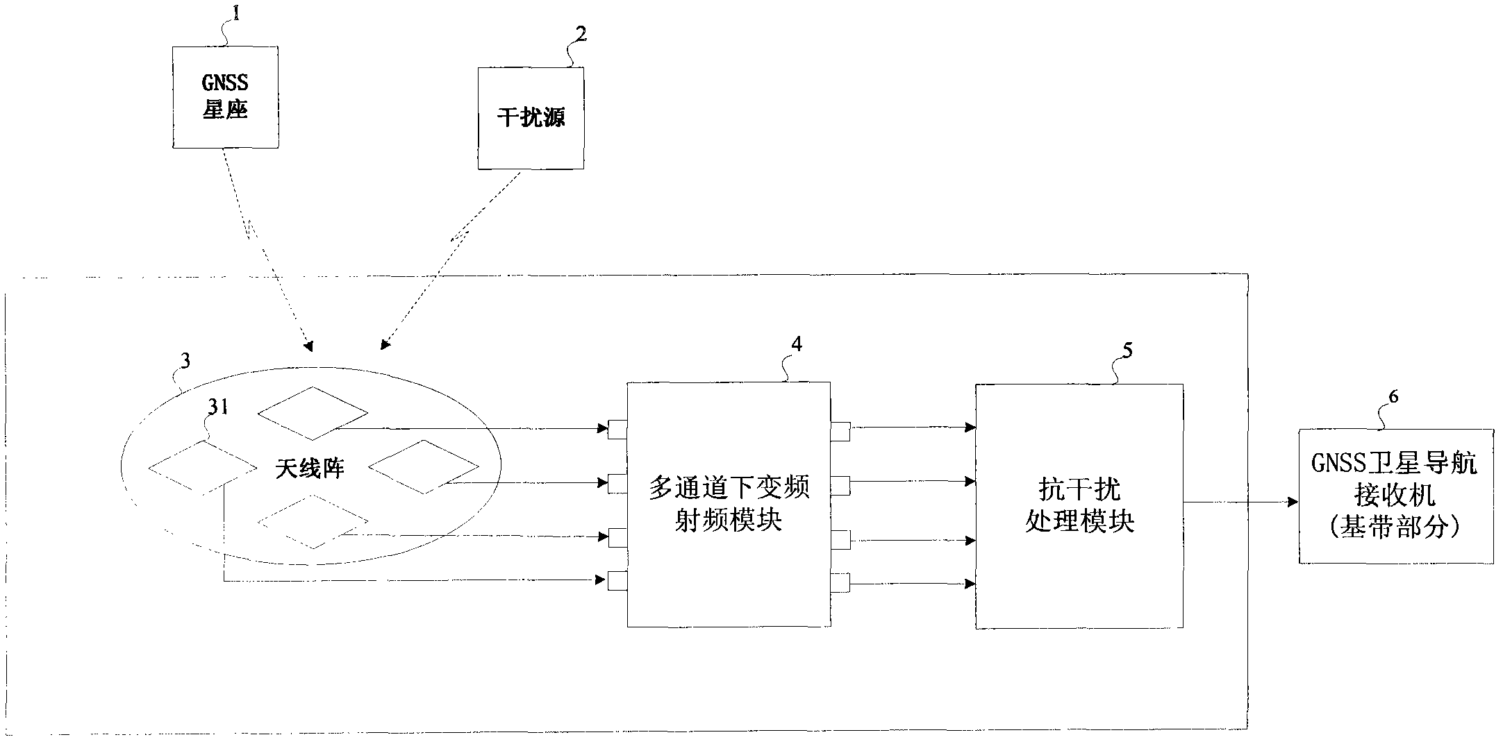
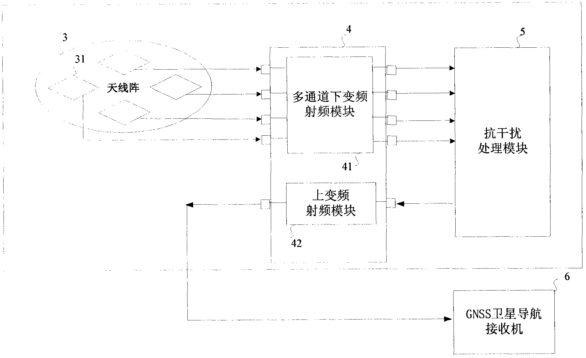
[0049] like figure 1 As shown, it is a structural schematic diagram of an embodiment of the anti-interference system of the present invention, including an antenna array 3 (note: the number of array elements 31 is variable, and it is a four-element array in the schematic diagram), a multi-channel down-conversion radio frequency module 4, and an anti-interference processing module 5 three main parts; the output of the anti-jamming system is connected with the baseband part 6 of the GNSS satellite navigation receiver. The multi-channel down-converting radio frequency module 4 is responsible for signal amplification and frequency conversion, converting the input GNSS carrier frequency signal to a low intermediate frequency for digital signal processing, and amplifying the signal to a level suitable for sampling; the output digital intermediate fre...


PUM


Abstract

The invention provides an anti-interference system and an anti-interference method based on digital beam forming and space-time zeroing cascade. The method is to cascade the digital beam forming and space-time zeroing, thus, the interference resistance of the whole system can be improved. The anti-interference system comprises an antenna array, a radio frequency module and an anti-interference processing module which are connected in sequence, wherein the anti-interference processing module comprises a digital beam forming module and a space-time zeroing processing module; the digital beam forming module is used for weighting and synthesizing various antenna array element signals into a reference beam signal pointed to a satellite, and synchronously obtaining an orthogonal vector signal orthogonal to a steering vector; output of the digital beam forming module is cascaded to the space-time zeroing processing module; and the space-time zeroing processing module is used for carrying out self-adaptive zeroing interference resistance processing to an interference signal in the reference beam signal, removing the interference signal in the reference beam signal, and outputting an effective satellite signal.

Description

technical field [0001] The invention relates to the technical field of satellite navigation, in particular to a satellite navigation anti-jamming system and method based on digital beamforming and space-time zeroing cascade. Background technique [0002] Currently, GNSS (Global Navigation Satellite System) mainly includes GPS in the United States, GLONASS in Russia, Beidou system in China, and GALILEO system in Europe. The signal of the Global Navigation Satellite System (GNSS) is generally easy to be interfered when received. Taking the GPS in the United States as an example, if the interference power exceeds the received power of the GPS signal by 24dB, the C / A code receiver of the commercial GPS cannot keep track of the signal. Tests have shown that a jammer with a power of 1W can disable the C / A code receiver within 85 kilometers. [0003] Many scenarios place high requirements on the anti-jamming of GNSS receivers. For GNSS differential network base stations, receive...

Claims


Application Information

Patent Timeline
Patent Type & Authority Applications(China)
IPC IPC(8): G01S19/21
Inventor 不公告发明人
Owner 北京北方联星科技有限公司
Why Eureka
Try Eureka