A Method for Determining Microdischarge Threshold of Coaxial Structure

A coaxial structure, micro-discharge technology, applied in electrical digital data processing, special data processing applications, instruments, etc., can solve the problems of not considering the velocity distribution and phase distribution, unable to describe the characteristics of secondary electron emission, long calculation time, etc.

Active Publication Date: 2015-08-05
XIAN INSTITUE OF SPACE RADIO TECH
View PDF2 Cites 0 Cited by
  • Summary
  • Abstract
  • Description
  • Claims
  • Application Information

AI Technical Summary

Problems solved by technology

[0004] However, the shortcomings of the above existing methods are mainly reflected in: (1) the velocity distribution and phase distribution when the electrons are actually emitted are not considered; (2) a fixed secondary electron emission model or simple fixed parameters to describe the secondary electron emission are used , so that the secondary electron emission characteristics of the actual component surface cannot be described, resulting in deviations in the calculated microdischarge threshold of microwave components; (3) The calculation time is long, which is not conducive to providing reference for the design of microwave components with high microdischarge threshold

Method used


Image

  • A Method for Determining Microdischarge Threshold of Coaxial Structure
  • A Method for Determining Microdischarge Threshold of Coaxial Structure
  • A Method for Determining Microdischarge Threshold of Coaxial Structure

Examples


Embodiment Construction

[0074] The present invention will be further described in detail below in conjunction with specific examples.

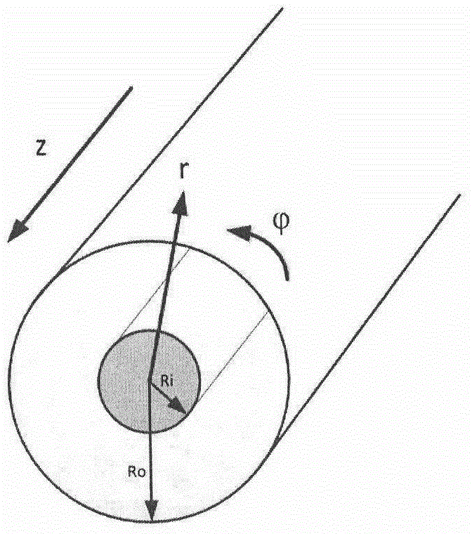
[0075] Assume that the coaxial transmission line outer diameter Ro=3.55mm, inner diameter Ri=1.54mm, RF field frequency f=1.6GHz, discharge gap d=Ro-Ri=2.01mm, angular frequency ω=2πf=10 10 rad / s, applied voltage U between inner and outer conductors 0 =200V.

[0076] Let m=200, T=1 / 1.6GHz=0.625ns, h=3.125×10 -12 s. t 1,2,…,m =3.125×10 -12 s,6.25×10 -12 s,...,6.25×10 -10 s.

[0077] The structure diagram of the coaxial transmission line is as follows: figure 2 Shown, concrete steps of the present invention are as follows:

[0078] Follow step one:

[0079] When the coaxial transmission line transmits the main mode, the internal electromagnetic field distribution is:

[0080] E r = U 0 r ln ( ...


PUM


Abstract

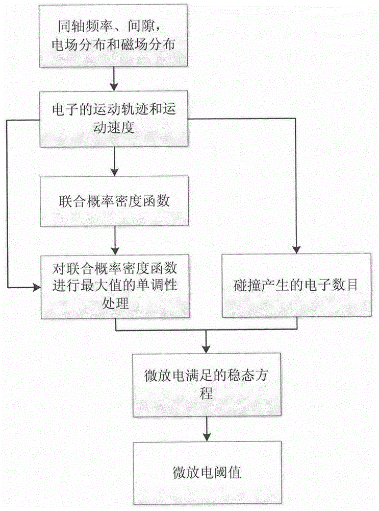
The invention discloses a method for determining a coaxial configuration micro-discharging threshold value. The method comprises the following steps of: determining an electronic movement locus and an electronic movement speed in a coaxial structure; converting probability of an emergence speed satisfying Maxwellian distribution into a joint probability density function of transit time; respectively carrying out maximum value and monotonicity processing to four classes of probability density functions to obtain a processed joint probability density function; taking an electron collision kinetic energy as an incidence electron energy of a secondary electron emission characteristic of a material to obtain a secondary electron multiplication function generated during electron collision under the transit time; constructing a steady-state equation which satisfies the electron number during micro discharging; judging whether a voltage generates micro discharging by solving an effective secondary electron multiplication rate in the steady-state equation; and gradually calculating an effective multiplication rate of a next voltage with a bisection method, wherein a corresponding voltage is a micro-discharging threshold value when the effective multiplication rate is 1. According to the method disclosed by the invention, an accurate micro-discharging threshold value can be obtained, and meanwhile, the threshold value can be quickly obtained.

Description

technical field [0001] The invention relates to a method for determining the micro-discharge threshold of a coaxial structure, which is suitable for the design of microwave components with a coaxial structure without micro-discharge and the prediction of the micro-discharge threshold of the microwave components with a coaxial structure. Background technique [0002] The micro-discharge effect is also called the secondary electron multiplication effect, which means that the component is at 1×10 -3 When the pressure is Pa or lower, the resonant discharge phenomenon occurs under the condition of high power. High-power microwave components in spacecraft loads, such as output multiplexers, filters, switch matrices, and antenna feeds, are prone to micro-discharge effects. Once micro-discharge effects occur, serious consequences will occur: noise levels increase and output power decreases The standing wave ratio of the microwave transmission system increases, the reflected power i...

Claims


Application Information

Patent Timeline
Patent Type & Authority Patents(China)
IPC IPC(8): G06F19/00
Inventor 张娜崔万照林舒李永东
Owner XIAN INSTITUE OF SPACE RADIO TECH
Why Eureka
Try Eureka