Seal checking method and seal checking device

A technology of a calibration device and a calibration method, which is applied in the directions of instruments, inductive record carriers, character and pattern recognition, etc., to achieve the effects of high speed, reduced workload, and reduced probability of calibration errors

Active Publication Date: 2013-01-16
SHENZHEN MAXVISION TECH
View PDF6 Cites 9 Cited by
  • Summary
  • Abstract
  • Description
  • Claims
  • Application Information

AI Technical Summary

Problems solved by technology

[0005] In view of the above-mentioned defects of the traditional verification technology, the purpose of the present invention is to provide a seal verification method and its device, which can solve the following problems: the workload of manual operations for daily v

Method used


Image

  • Seal checking method and seal checking device
  • Seal checking method and seal checking device
  • Seal checking method and seal checking device

Examples


Embodiment 1

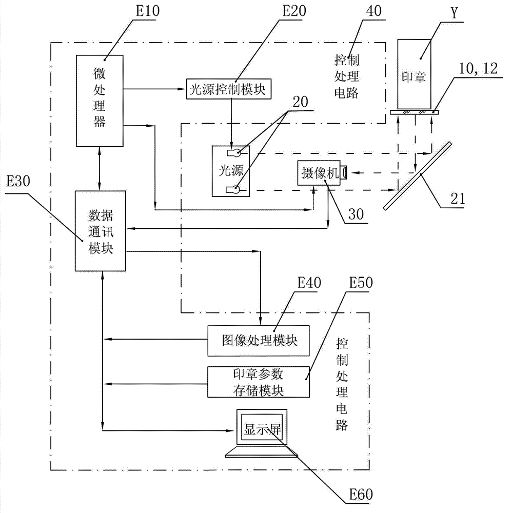
[0067] Such as figure 2 , which is a schematic circuit block diagram of Embodiment 1 of the seal verification device of the present invention. It includes a transparent window 10 for framing the impression of the stamp Y to be inspected. The device is provided with n groups of light sources 20 that project light to the impression of the stamp Y in a circular distribution, and a camera for taking pictures of the impression. Camera 30, controlling n groups of light sources 20 and the control processing circuit 40 for cooperating with cameras 30 and processing impression images; between the transparent window and the optical path of the light source 20 and camera 30, an oblique plane mirror 21 for turning light is provided; The control processing circuit 40 includes: a microprocessor E10, a light source control module E20, a data communication module E30, an image processing module E40, a storage module E50 for storing stamp parameters, a display screen E60; the controlled end o...

Embodiment 2

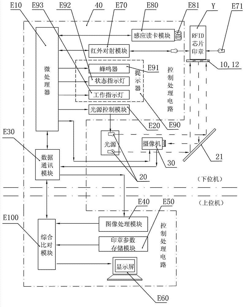
[0070] Such as image 3 , which is a schematic block diagram of the circuit structure of Embodiment 2 of the seal verification device of the present invention. On the basis of Embodiment 1, it has the following further circuit structure improvements:

[0071]The seal Y is provided with an RFID electronic tag Y10; the control processing circuit 40 also includes an infrared through-shooting module E70 connected to an infrared through-shooting lamp E71, an induction card reading module E80 connected to an induction coil E81, a prompter E90, and a comprehensive comparison Module E100; the I / O port of the infrared radiation module E70, the I / O port of the inductive card reader module E80, and the input end of the prompter E90 are respectively connected to the corresponding interface of the microprocessor E10; the image processing module E40 The output end of the storage module E50 and the input end of the display screen E60 are respectively connected to the corresponding ports of ...


PUM


Abstract

The invention relates to a seal checking method and a seal checking device. The checking device comprises n groups of light sources, a camera and a control processing circuit which are distributed annularly. The checking method comprises the following steps: the n groups of light sources are started in sequence based on time sequence so as to realize flash exposure of a die of the seal; the camera synchronously shoots the die of the seal during exposure, so as to obtain n electronic images Fi, brightness values of the n electronic images are compared, and then the brightest electronic image Flight and the darkest electronic image Fdark are selected from the n electronic images; the brightest electronic image Flight and the darkest electronic image Fdark are aligned to realize pixel stacking and composition of the images; the composite electronic image Ftarget is subjected to check and verification with a stored target image and stored target parameters, and then a check pass signal or a check rejection signal is sent. According to the seal checking method and the seal checking device, the daily manual operation workload of seal checking is greatly reduced, the seal checking efficiency is increased greatly, the checking failure probability is reduced, the operation is simplified, the paperless office work is significantly promoted, and the daily consumption of paper is lowered.

Description

technical field [0001] The invention relates to electronic monitoring equipment, and more particularly, the invention relates to an electronic equipment for identifying and monitoring management seals. Background technique [0002] The use of seals generally involves major property interests and even personal safety of relevant units, enterprises, and individuals. For border inspections, ports and other units that involve national public security and national interests, the verification and identification technology of verification stamps is particularly important. In order to check and control the large number of people and goods entering and exiting the border inspection and ports, the relevant inspection personnel must frequently use the inspection stamps to sign and release the personnel and goods entering and leaving. The complete and correct information on the inspection stamp provides effective evidence for the border inspection and port units to implement correct ins...

Claims


Application Information

Patent Timeline
IPC IPC(8): G06K9/64G06K7/00
Inventor 瞿磊
Owner SHENZHEN MAXVISION TECH
Why Eureka
Try Eureka