Vibration power generating device and manufacturing method thereof

A technology of vibration power generation and manufacturing method, which is applied in the field of micro energy, can solve the problems that cannot meet the development requirements of wireless sensor network and mobile communication equipment, the size of piezoelectric sheet is limited, and the power generation effect is limited, so as to achieve good power generation effect and low weight Lightweight, the effect of improving power generation efficiency

Inactive Publication Date: 2013-01-16
BEIJING JIAYUE TONGLEJI ELECTRONICS
View PDF0 Cites 8 Cited by
  • Summary
  • Abstract
  • Description
  • Claims
  • Application Information

AI Technical Summary

Problems solved by technology

Therefore, the use of traditional batteries can no longer meet the development requirements of wireless sensor networks and mobile communication equipment
[0003] Therefore, there is a need for a micro power generation device that can provide long-term reliable self-powered energy for micro-nano systems, by absorbing mechanical energy (such as vibration, wind energy, airflow energy, etc.) and / or heat energy, solar energy, static energy, etc. in the environment. Power output is generated in its corresponding system, and the existing micro power generation devices generally include piezoelectric vibration power generation devices, magnetoelectric vibration power generation devices or electrostatic vibration power generation devices. However, in such power generation devices, the vibration medium is often installed on the cantilever beam , in this way, often due to the small displacement caused by the bending of the cantilever, the power generation effect is limited, and the size of the cantilever beam is limited, which also makes the vibration medium, especially the size of the piezoelectric sheet in piezoelectric vibration power generation, which affects the power generation efficiency.

Method used


Image

  • Vibration power generating device and manufacturing method thereof
  • Vibration power generating device and manufacturing method thereof
  • Vibration power generating device and manufacturing method thereof

Examples


Embodiment Construction

[0059] In order to describe the technical content, structural features, achieved goals and effects of the present invention in detail, the following will be described in detail in conjunction with the embodiments and accompanying drawings.

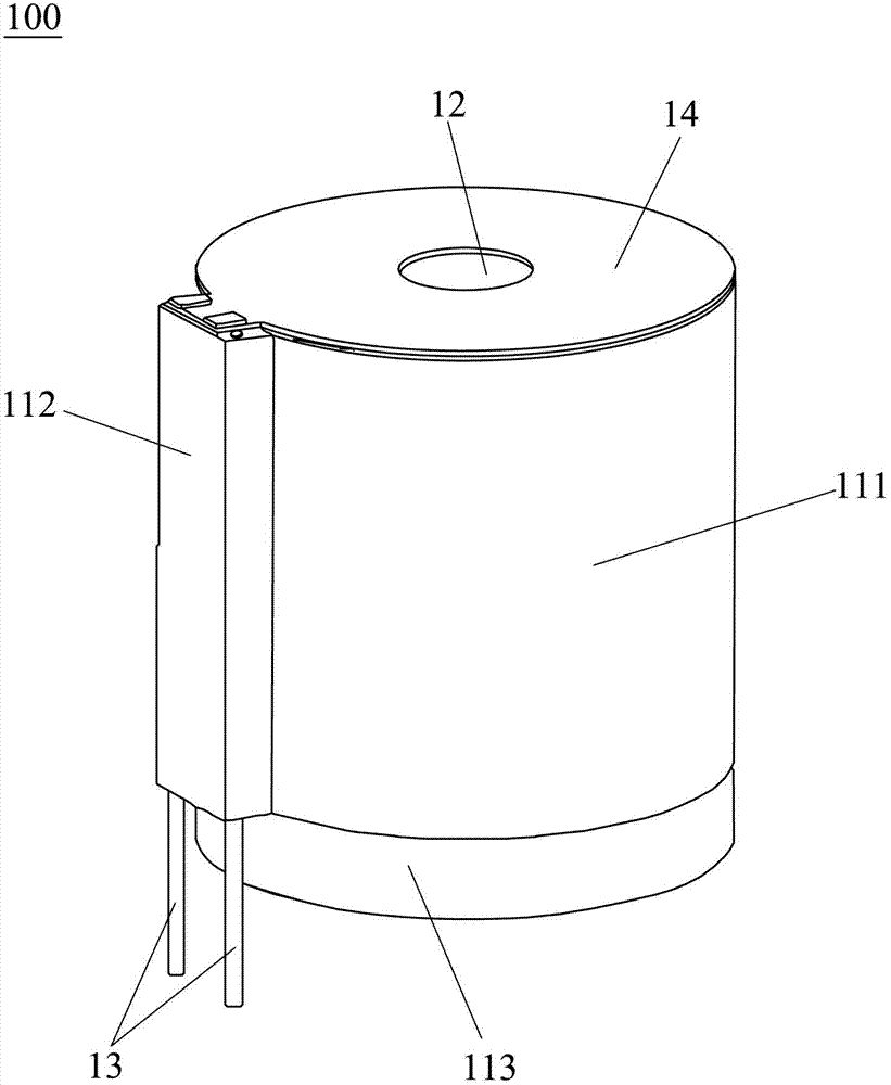
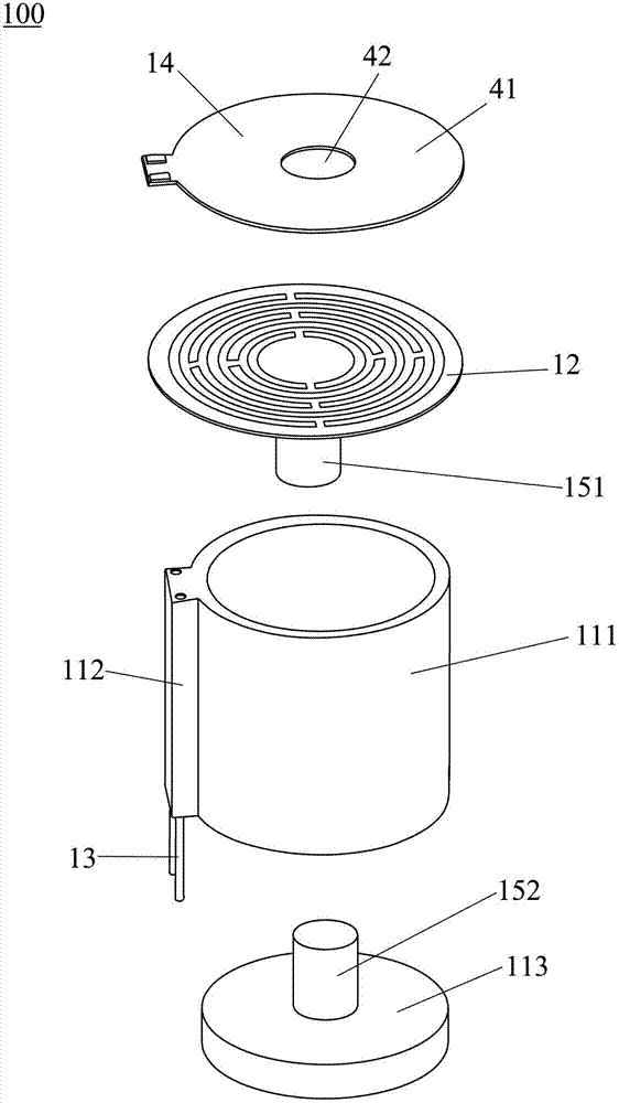
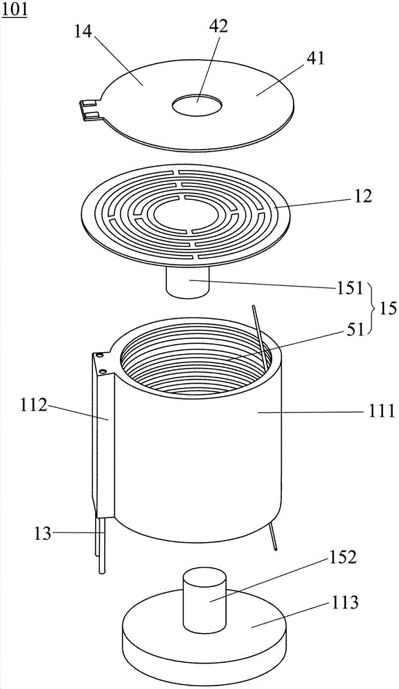
[0060] refer to figure 1 and figure 2 , showing the first embodiment of the vibration power generation device of the present invention. The vibration power generation device 100 includes a support 11, an elastic plate 12, a conductive welding pin 13, a power generation component and a resistance system, the support 11 has a cavity 111, and one end of the cavity 111 has an opening; the elastic plate 12 is mounted on At the opening of the cavity 111, the cavity 111 supports the periphery of the elastic plate 12, and a mass block 151 is installed in the center of the elastic plate 12, and the mass block 151 drives the elastic plate 12 when vibrating. The plate 12 moves in a direction perpendicular to the elastic plate 12; the conductive we...


PUM

PropertyMeasurementUnit
thicknessaaaaaaaaaa

Abstract

The invention discloses a vibration power generating device. The device comprises a bracket, an elastic plate, conductive welding needles and power generating parts, wherein a cavity is formed in the bracket, and one end of the cavity is provided with an opening; the elastic plate is arranged at the opening of the cavity, so that the cavity supports the edge of the elastic plate; a quality block is arranged in the center of the elastic plate; and the power generating parts comprise one or a combination of two or more than two of the parts, namely a piezoelectric part, a magnetoelectricity part, an electrostatic part and an electret part. By the device, a plurality of kinds of relatively independent output power are integrated to output electricity, long-term reliable autonomous power is provided for a micro-nano system, service life of the device is prolonged, and the device has high power generating efficiency and small size, and is low in cost, economic and environment-friendly; and in addition, the elastic plate drives the quality block to move along the vertical direction of the elastic plate when vibrating, and the power generating efficiency is high. The invention also discloses a manufacturing method for the vibration power generating device.

Description

technical field [0001] The invention belongs to the field of micro-energy technology, and in particular relates to a vibration power generation device with high power generation efficiency. Background technique [0002] The rapid development and application of micro-nano electromechanical system (MEMS, NEMS) technology has driven the development of wireless sensor network technology, and has gradually realized commercial applications in the fields of industry, aerospace, communication, commerce, consumption and military affairs, but there are still challenges A very serious problem is how to ensure the power supply of these wireless sensing units and mobile communication equipment. The more popular practice in traditional industries is to use batteries. Due to the large number of unit devices that constitute wireless sensor networks and mobile communication equipment, their small size and scattered locations, this requires their power supply devices to be small in size, high...

Claims


Application Information

Patent Timeline
Patent Type & Authority Applications(China)
IPC IPC(8): H02N2/18H02K35/02B81C1/00
Inventor 冯淑兰彭春雷
Owner BEIJING JIAYUE TONGLEJI ELECTRONICS
Why Eureka
Try Eureka