Parking lock mechanism for power transmission system

A technology of a power transmission device and a parking lock mechanism, which is applied to transmission parts, transmission control, braking components, etc., can solve the problems of increased sliding resistance of the parking cam 115, and achieve low cost and reduced torque Capacity and the effect of preventing the deterioration of operation feeling

Inactive Publication Date: 2013-01-16
TOYOTA JIDOSHA KK
View PDF5 Cites 8 Cited by
  • Summary
  • Abstract
  • Description
  • Claims
  • Application Information

AI Technical Summary

Problems solved by technology

[0013] In such an existing parking lock mechanism, since the sliding surface of the parking cam 115 is not actively lubricated, that is, the sliding surface of the parking cam 115 again

Method used


Image

  • Parking lock mechanism for power transmission system
  • Parking lock mechanism for power transmission system
  • Parking lock mechanism for power transmission system

Examples


no. 1 approach )

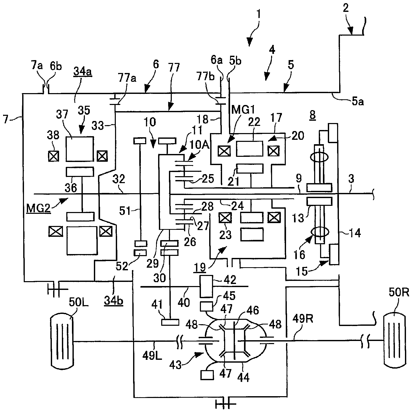
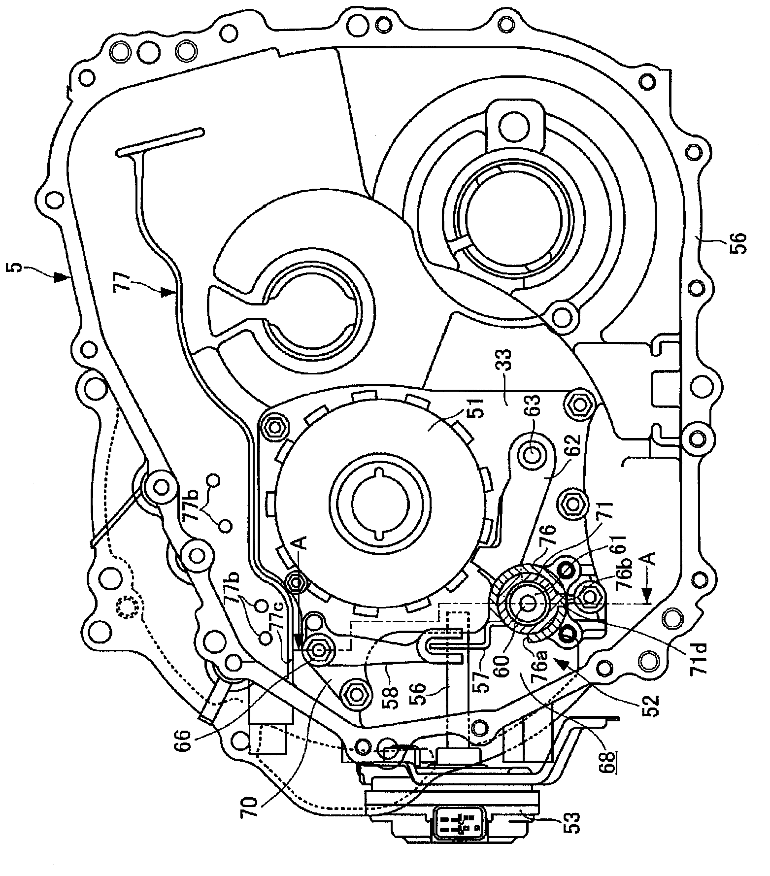
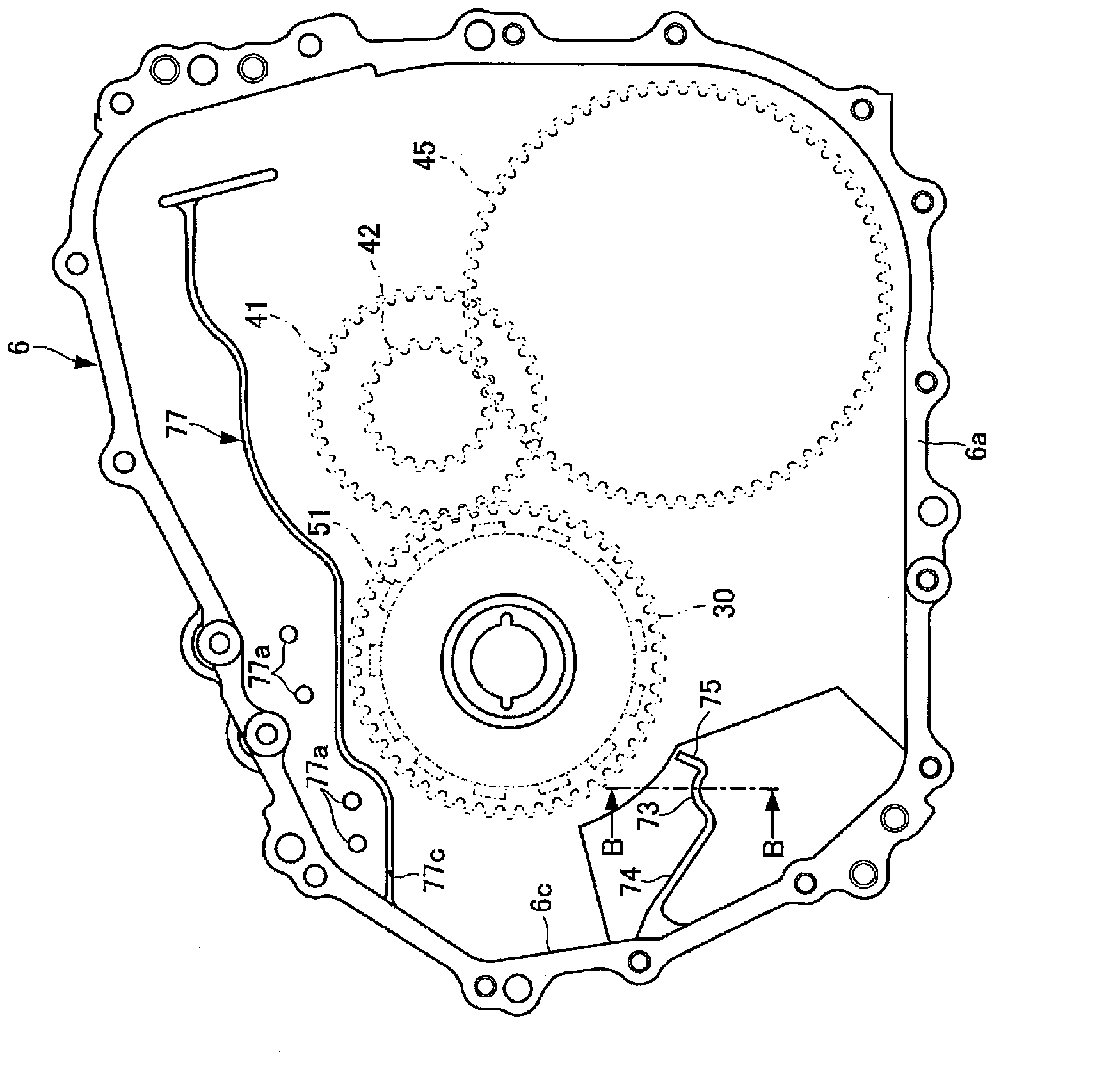
[0072] Figure 1~Figure 6 It is a figure which shows 1st Embodiment of the parking lock mechanism of the power transmission apparatus concerning this invention. In addition, in this embodiment, an example in which a parking lock mechanism is applied to a hybrid vehicle is shown.

[0073] First, the structure will be described.

[0074] exist figure 1 In the figure, there is a transaxle 1 as a power transmission device of a FF (Front Engine-Front drive) hybrid vehicle, and the transaxle 1 is connected to an engine 2 .

[0075] As the engine 2, a gasoline engine, a diesel engine, an LPG engine, a methanol engine, a hydrogen engine, or the like can be used as an internal combustion engine. In this embodiment, for simplicity, a case where a gasoline engine is used as the engine 2 will be described.

[0076] The engine 2 is a device that outputs power from a crankshaft 3 by burning fuel, and is a known product that includes an intake device, an exhaust device, a fuel injection...

no. 2 approach )

[0154] Figure 7~Figure 15 It is a figure showing the second embodiment of the parking lock mechanism of the power transmission device according to the present invention, and the same reference numerals are assigned to the same components as those of the first embodiment, and description thereof will be omitted.

[0155] exist Figure 7 In the expansion case 6, a cylindrical portion 81 as a cylindrical member and a second cylindrical member is provided. The cylindrical portion 81 abuts against one end portion of the sleeve 71 in the axial direction, thereby holding the sleeve 71 The sleeve 71 is positioned on the extension case 6 so as to support the sleeve 71 on the engine side case 5 and the extension case 6 .

[0156] The cylindrical part 81 has an inner peripheral part 81a as a second inner peripheral part communicating with the inner peripheral part 71a of the sleeve 71, and an upper notch 81b is formed on the upper part of the cylindrical part 81, and the upper notch 81...

no. 3 approach )

[0195] Figure 16~Figure 18 It is a figure showing the third embodiment of the parking lock mechanism of the power transmission device according to the present invention, and the same reference numerals are assigned to the same components as those of the first embodiment, and description thereof will be omitted.

[0196] exist Figure 16 , Figure 17 Among them, the motor generator MG2 as a rotating electrical machine faces one surface of the partition wall 33 that defines the motor housing chamber 34a together with the engine side case 5 and the end cover 7, and the other face of the partition wall 33 that faces the sleeve 71 A cylindrical portion 91 serving as a cylindrical member and a second cylindrical member is formed on the surface.

[0197] The cylindrical portion 91 has an inner peripheral portion 91a as a second inner peripheral portion communicating with the inner peripheral portion 71a of the sleeve 71, and an upper notch 91b is formed on the upper portion of the...


PUM


Abstract

Provided is a parking lock mechanism for a power transmission system such that lubricating oil can be stably supplied to the sliding surface of a parking cam, resulting in the sliding resistance of the parking cam being reduced. The parking lock mechanism (52) is such that a support section (73) for positioning a sleeve (71) in an extension housing (6) is provided with a first guide rib (74) which catches oil circulating in a transmission axle case (4) and supplies said oil to the support section (73), that furthermore, a cutout (71c) for causing a parking pawl (62) to abut a parking cam (61) is formed in the upper portion of the sleeve (71), and that the oil caught by the first guide rib (74) is supplied via the support section (73) and the cutout (71c) in the sleeve (71) to the sliding surfaces of the parking cam (61), that is, to the sliding surface between the parking pawl (62); and the parking cam (61) and to the sliding surface between the parking cam (61) and the sleeve (71).

Description

technical field [0001] The present invention relates to a parking lock mechanism of a power transmission device, and more particularly to a parking lock mechanism of a power transmission device capable of preventing rotation of a rotating member of a power transmission device of a vehicle such as an automobile. Background technique [0002] The power transmission device of a vehicle such as an automatic car is equipped with a parking lock mechanism. If the vehicle is manually shifted from the driving gear to the parking gear when the vehicle is parked, the parking lock claw and the parking gear installed on the rotating shaft of the power transmission device Engaged, the rotating shaft is locked so that it cannot rotate. [0003] As a conventional parking lock mechanism of this type, known Figure 21 As shown (for example, refer to Patent Document 1). [0004] exist Figure 21 Among them, there are provided: a stop lever 111 integrated with a manual lever (not shown) that r...

Claims


Application Information

Patent Timeline
IPC IPC(8): B60T1/06F16H63/34
CPCB60T1/005F16H57/0494B60W10/182F16H57/0423F16H63/3416F16H57/0467
Inventor 木村弘道土田充孝北畑刚小畑达郎铃木阳介桑原毅
Owner TOYOTA JIDOSHA KK
Why Eureka
Try Eureka