Finned tube locating fixture and assembly method of heat exchanger
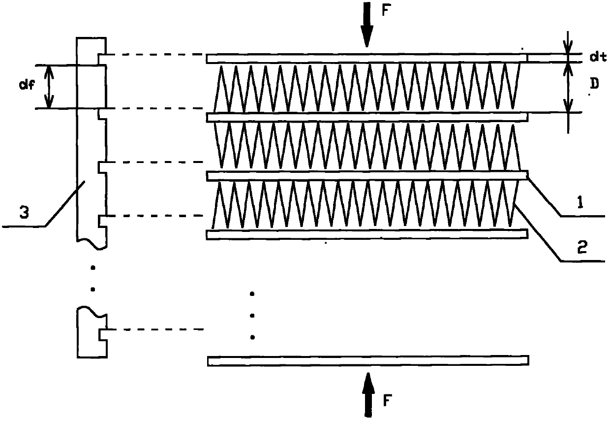
A technology for positioning tooling and heat exchangers, applied in workpiece clamping devices, metal processing, manufacturing tools, etc., can solve the problems of easy dislocation of flat tubes, low operation efficiency, etc., achieve simple and reasonable structure design, improve production efficiency and accuracy Effect
- Summary
- Abstract
- Description
- Claims
- Application Information
AI Technical Summary
Problems solved by technology
Method used
Image
Examples
Embodiment 1
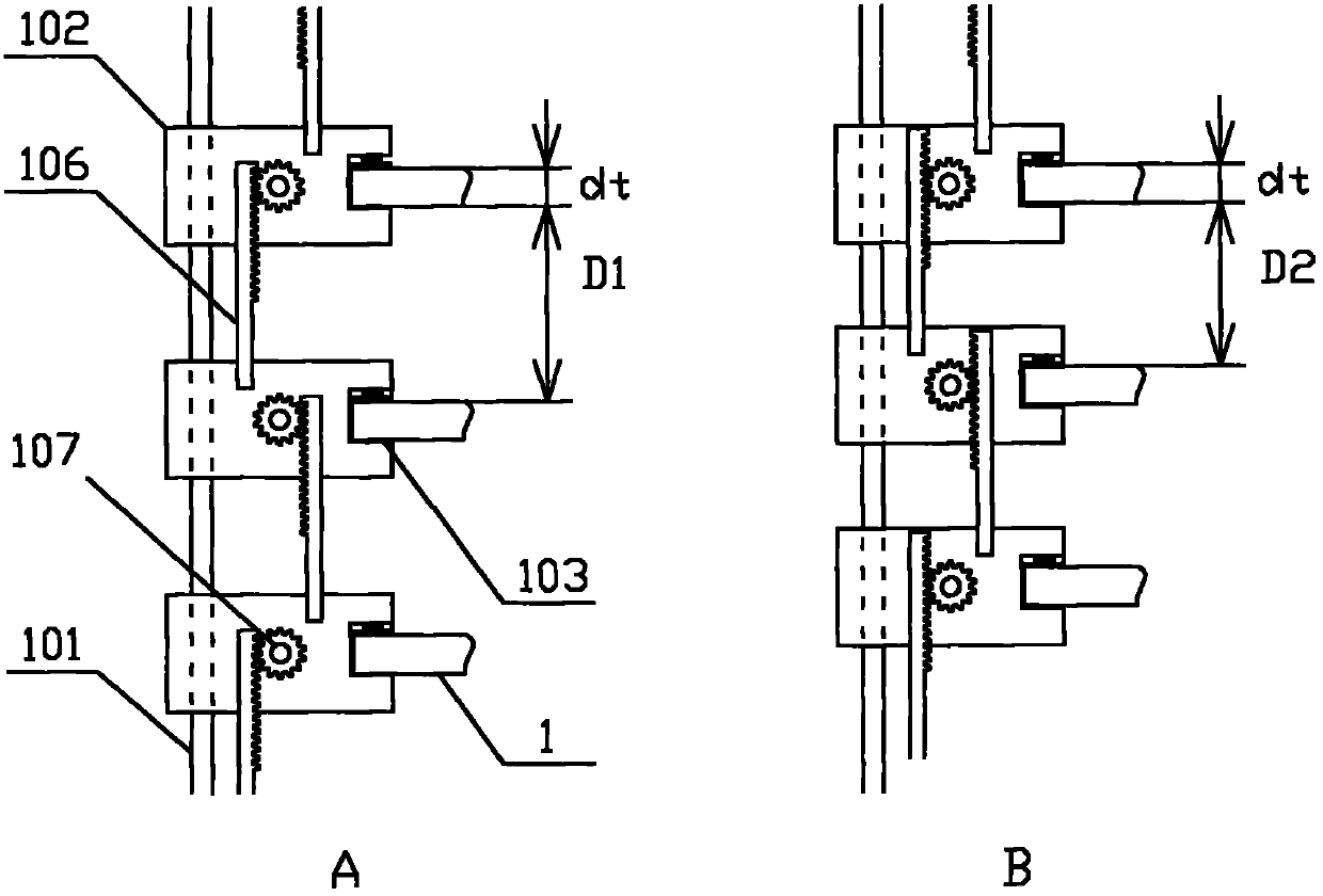
[0048] This embodiment provides an implementation scheme and an assembly method of a quick positioning tool for tube fins of a heat exchanger.
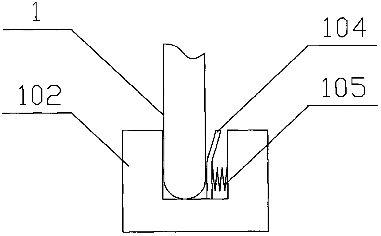
[0049] This embodiment provides a tube fin positioning tool for heat exchanger, as attached figure 2 As shown, it includes a bracket 101, a driving mechanism and a set of sliders 102 for fixing flat tubes. The slider 102 is installed on the bracket 101 and can move along the axis of the bracket 101 . The sliders 102 are provided with racks 106 , and adjacent sliders are meshed with each other through the racks 106 and gears 107 . attached figure 2 It is only a schematic structural diagram of this embodiment, which has been simplified without affecting the understanding of the technical solutions of the embodiment. The bracket 101 in the figure only shows the fixed shaft connected to the slider, omitting the main body of the bracket and appendix. Similarly, in all the drawings, several tube fins are used to express the technical so...
Embodiment 2
[0061] This embodiment provides an implementation scheme and an assembly method of a quick positioning tool for tube fins of a heat exchanger.
[0062] This embodiment provides a tube fin positioning tool for a heat exchanger, such as Figure 4 As shown, it includes a slider bracket 201 , a set of sliders 202 , a tube holder composed of a bottom plate 203 and a tie rod 204 , a tie rod shaft 205 and a pressure plate 206 . The slider 202, the bottom plate 203, the pull rod 204, the pull rod shaft 205 and the pressing plate 206 together form a driving mechanism for driving the movement of the tube fin.
[0063] The pipe holder is a chute formed by the bottom plate 203 and the pull rod 204. One end of the chute is fixed, and the other end is provided with a wrench which can be turned to change the height of the chute. The width of the pull rod matches the thickness of the installed flat tube, and the flat tube can be fixed by inserting it on the chute. After the fin assembly is c...
Embodiment 3
[0074] This embodiment provides an implementation scheme and an assembly method of a quick positioning tool for tube fins of a heat exchanger.
[0075] This embodiment provides a tube fin positioning tool for heat exchanger, as attached Figure 8 As shown, it includes a bracket 301, a driving mechanism and a set of sliders 302 for fixing the flat tube.
[0076] The slider 302 is installed on the bracket 301 and can move along the axis of the bracket 301 . A slot 303 matching the thickness of the flat tube is also provided on the slider 302 to fix the flat tube 1 of the heat exchanger. A gasket 304 is provided on one side of the slot 303 . Using different thicknesses or numbers of spacers, the thickness of the slots or grooves can be adjusted to accommodate flat tubes of different thicknesses.
[0077] The driving mechanism in this embodiment is composed of a cam 305 between adjacent sliders and a connecting rod 306 connecting the sliders and the cam. Turning the cam 305 dr...
PUM
 Abstract
Description
Claims
Application Information
 - R&D
- Intellectual Property
- Life Sciences
- Materials
- Tech Scout
- Unparalleled Data Quality
- Higher Quality Content
- 60% Fewer Hallucinations
Browse by: Latest US Patents, China's latest patents, Technical Efficacy Thesaurus, Application Domain, Technology Topic, Popular Technical Reports.
© 2025 PatSnap. All rights reserved.Legal|Privacy policy|Modern Slavery Act Transparency Statement|Sitemap|About US| Contact US: help@patsnap.com


