Spectral synchronous phase-shift common-path interference microscopic-detection device and detection method

A synchronous phase-shifting and interference microscopy technology, which is applied to measuring devices, optical devices, instruments, etc., can solve problems such as low measurement accuracy and complicated operation, and achieve simple mapping relationship, convenient and flexible operation, and simple device structure Effect

Inactive Publication Date: 2013-01-23
HARBIN ENG UNIV
View PDF4 Cites 15 Cited by
  • Summary
  • Abstract
  • Description
  • Claims
  • Application Information

AI Technical Summary

Problems solved by technology

[0006] The purpose of the present invention is to solve the problems of complex operation and low measurement accuracy of the existing optical phase-shifting inter

Method used


Image

  • Spectral synchronous phase-shift common-path interference microscopic-detection device and detection method
  • Spectral synchronous phase-shift common-path interference microscopic-detection device and detection method
  • Spectral synchronous phase-shift common-path interference microscopic-detection device and detection method

Examples


specific Embodiment approach 1

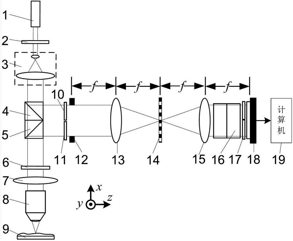
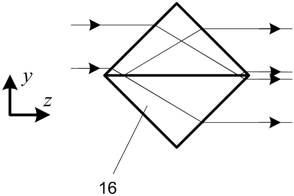
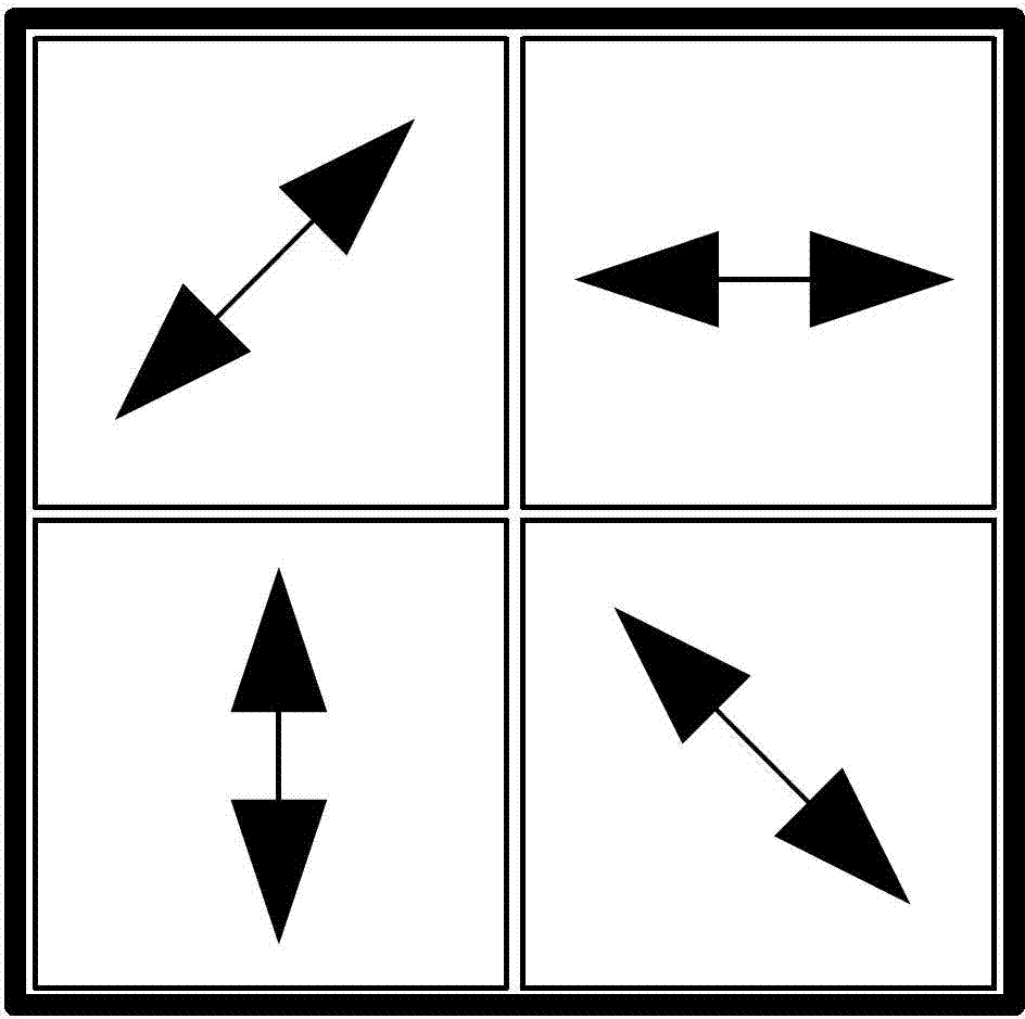
[0038] Specific implementation mode one: the following combination Figure 1 to Figure 4 Illustrate this embodiment mode, the light-splitting synchronous phase-shift common optical path interference microscope detection device described in this embodiment mode, it comprises light source 1, it also comprises polarizer 2, collimation beam expander system 3, first beam-splitting prism 4, the second beam-splitting prism Prism 5, first λ / 4 wave plate 6, correction objective lens 7, microscope objective lens 8, object to be measured 9, second λ / 4 wave plate 10, third λ / 4 wave plate 11, rectangular window 12, first Fourier lens 13, one-dimensional periodic grating 14, second Fourier lens 15, depolarization beam splitter prism 16, four-quadrant polarizer group 17, image sensor 18 and computer 19, wherein λ is the light wavelength of light source 1 emitting light beam ,

[0039] The light beam emitted by the light source 1 enters the light receiving surface of the collimated beam expa...

specific Embodiment approach 2

[0049] Specific implementation mode two: the following combination figure 2 Describe this embodiment mode, this embodiment mode will further illustrate Embodiment 1, the first dichroic prism 4 and the second dichroic prism 5 are non-polarizing dichroic prisms, the second λ / 4 wave plate 10 and the third λ / 4 wave plate 11 The direction of the fast axis is the same.

specific Embodiment approach 3

[0050] Specific embodiment three: this embodiment will further illustrate embodiment one or two, the first dichroic prism 4 and the second dichroic prism 5 are polarization beam splitters, the second λ / 4 wave plate 10 and the third λ / 4 wave The directions of the fast axes of the sheets 11 are perpendicular to each other.


PUM


Abstract

The invention discloses a spectral synchronous phase-shift common-path interference microscopic-detection device and a detection method, which belongs to the field of optical interference detection. The invention is designed for solving the problem that the existing optical phase-shift interference detection method is complicated and difficult in operation and low in measurement accuracy. The scheme of the invention is as follows: a beam emitted by a light source, after passing through a polaroid, enters into a light receiving surface of a beam collimating and expanding system, after the beam is subjected to beam collimating and expanding by the beam collimating and expanding system, an emergent beam enters into a first beam splitter prism, and then a reflected beam of the first beam splitter prism, as a reference beam, enters into a rectangular window after passing through a second lambda/4 wave plate; the reference beam and object beams which are abreast converged into the rectangular window respectively pass through a first Fourier lens, a one-dimensional periodic grating, a second Fourier lens, a non-polarizing beam splitter prism and a four-quadrant polaroid set again, a polarized beam emitted from the four-quadrant polaroid set generates an interference pattern on a plane of an image sensor, and a computer carries out processing on the acquired interference pattern so as to obtain the phase distribution of an object to be detected.

Description

technical field [0001] The invention relates to a light-splitting synchronous phase-shift common optical path interference microscopic detection device and a detection method, belonging to the field of optical interference detection. Background technique [0002] Interference microscopy combines interference technology and microscopic magnification technology, which can accurately analyze the three-dimensional shape of objects and the phase information of phase-type objects. It is an ideal method for measuring the three-dimensional shape and phase distribution of tiny objects. [0003] In 2006, the Swiss company Lyncee Tec launched the DHM-1000 digital holographic microscope for the first time, which can be used to measure the three-dimensional shape and phase distribution of tiny objects. However, due to the off-axis holographic optical path, the CCD resolution and spatial bandwidth product cannot be fully utilized; at the same time, the phase distortion caused by the obje...

Claims


Application Information

Patent Timeline
IPC IPC(8): G01B9/02G01B11/24
Inventor 单明广钟志郝本功张雅彬窦峥刁鸣
Owner HARBIN ENG UNIV
Why Eureka
Try Eureka