Vibration circular disc type no-tillage anti-blocking device

A disc-type, anti-blocking technology, which is applied to fertilization devices, seeding, planter parts, etc., can solve the problems of driving anti-blocking devices such as high noise, poor safety performance, and poor soil penetration ability, and achieves small soil disturbance and cutting Strong capacity and low soil disturbance effect

Inactive Publication Date: 2014-11-19
CHINA AGRI UNIV
View PDF13 Cites 0 Cited by
  • Summary
  • Abstract
  • Description
  • Claims
  • Application Information

AI Technical Summary

Problems solved by technology

[0006] The purpose of the present invention is to overcome the problems of the passive anti-blocking device in the background technology, such as poor soil entry ability, heavy weight, poor anti-blocking ability, high noise of driving the anti-blocking device, poor safety performance, and large amount of soil movement, etc., so as to effectively cut off the front of the opener. The straw and root stubble in the sowing belt have strong cutting ability, high passing performance of the whole machine, successfully complete fertilization, sowing and other operations, improve the quality of sowing, and provide a vibrating disc type no-tillage anti-blocking device, which is characterized in that the vibration The disc-type no-tillage anti-blocking device comprises a frame 1, an anti-blocking device 2, and a gearbox 5. In the frame 1, the frame front beam 101 and the frame rear beam 102 are parallel to each other, and 8 frame longitudinal plates 103 Parallel to each other, the front beam 101 of the frame is vertically fixed to the front ends of the 8 longitudinal plates 103 of the frame, the rear end of the frame rear beam 102 is vertically fixed to the rear ends of the 8 longitudinal plates 103 of the frame, the front beam 101 of the frame, the rear end of the frame 102 and 8 frame longitudinal plates 103 form the frame main body of the horizontal grid structure, from left to right, an anti-blocking device support beam is formed by two frame longitudinal plates 103, and the front portion of the frame longitudinal plate 103 has One pin hole 110, four anti-blocking device support beams are equally spaced and symmetrically distributed, the length of the frame rear beam 102 is greater than the length of the frame front beam 101, two side plates 104 are perpendicular to the frame rear beam 102, and two side plates 104 They are parallel to each other and fixed horizontally at the left and right ends of the rear beam 102 of the rack respectively. On the left side of the rear end of the beam 105 and on the right side of the rear cantilever beam 105 rear end of the right frame, a depth adjustment screw mounting plate 106 is vertically fixed respectively. Under the rear beam 102 of the frame, a rectangular frame structure The opener mounting frame 301 is fixed horizontally on the two left and right side plates 104 by the opener frame support plates 304 at both ends, and the opener frame front beam 302 and the opener frame rear beam 303 are parallel to the frame front beam 101 , along the same straight line parallel to the frame front beam 101, the four bearing housing mounting plates 107 are fixed horizontally from left to right to the first frame longitudinal plate 103, the second frame longitudinal plate 103, the seventh On the first rack longitudinal plate 103 and the eighth rack longitudinal plate 103, two gearbox mounting plates 109 are fixed horizontally on the fourth rack longitudinal plate 103 and the fifth rack longitudinal plate 103 respectively, and two The seed fertilizer box mounting plate 108 is symmetrically fixed on the side plates 104 on the left and right sides respectively, and the three-point suspension 6 is fixed on the frame front beam 101 and the frame rear beam 102;

Method used


Image

  • Vibration circular disc type no-tillage anti-blocking device
  • Vibration circular disc type no-tillage anti-blocking device
  • Vibration circular disc type no-tillage anti-blocking device

Examples


Embodiment Construction

[0023] The present invention will be further described in detail below in conjunction with the embodiments and the accompanying drawings. It should be emphasized that the following description is only exemplary and not intended to limit the scope of the invention and its application.

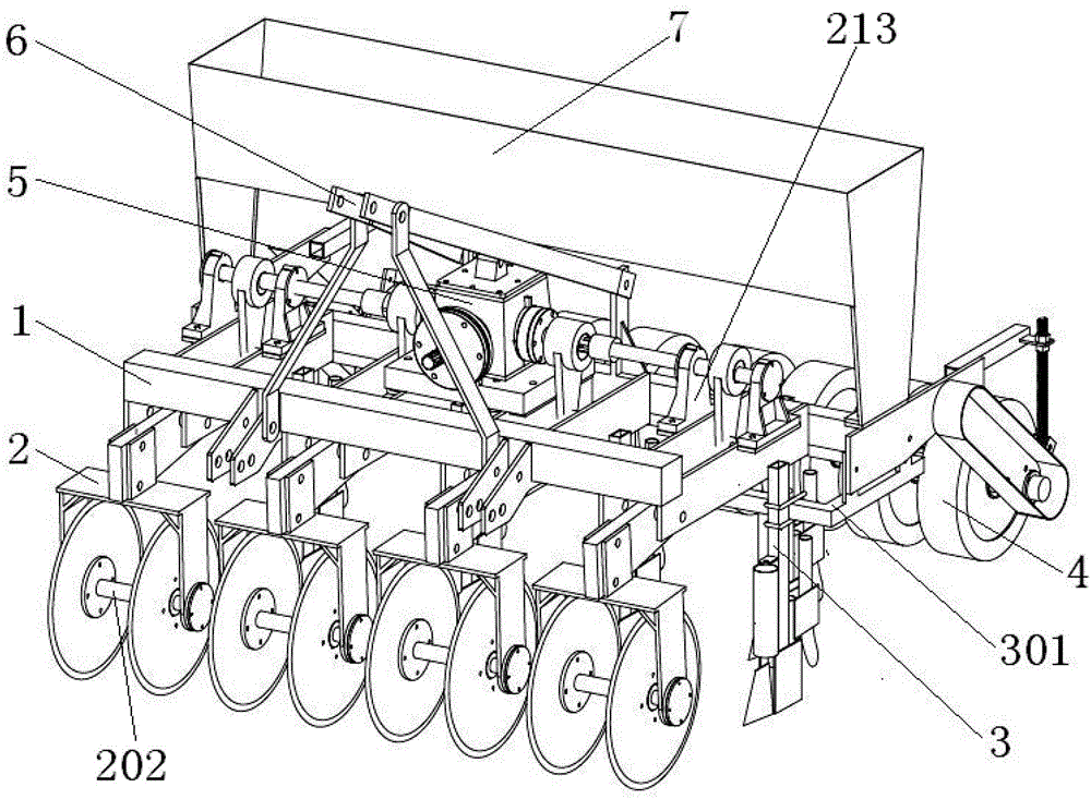
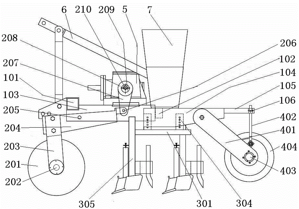
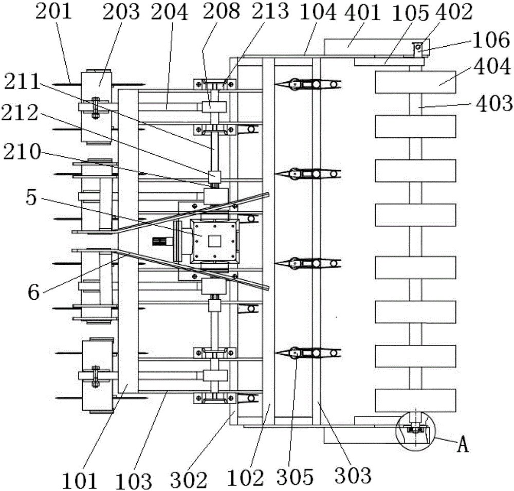
[0024] figure 1 It is a three-dimensional schematic diagram of a vibrating disc type no-tillage anti-blocking device used in a no-tillage planter embodiment. The vibrating disc type no-tillage anti-blocking device includes a frame 1, an anti-blocking device 2 and a gearbox 5. The vibrating disc type The no-tillage anti-blocking device is installed with a ditching device 3, a suppression mechanism 4 and a fertilizer box 7 to form a no-tillage seeder drawn by a tractor and powered. figure 2 and image 3 They are the schematic diagram of the front view and the schematic diagram of the top view of the vibrating disc type no-tillage anti-blocking device, respectively.

[0025] Such as Figure 4 ...


PUM


Abstract

The invention belongs to the technical field of agricultural machinery and relates to a vibration circular disc type no-tillage anti-blocking device The vibration circular disc type no-tillage anti-blocking device consists of a machine frame, an anti-blocking device and a gearbox, wherein the anti-blocking device comprises four anti-blocking units and each anti-blocking unit comprises a crank rocker rod mechanism consisting of an eccentric rolling tube, a first bearing, a rocker rod and a swinging rod, eccentric rolling tubes arranged in each anti-blocking unit are driven to rotate by the rotation of an output shaft of the gearbox and anti-blocking driving shafts, the eccentric rolling tubes drive the first bearing to do eccentric movement, the first bearing drives the rocker rods to do upward and downward reciprocating movement, the rocker rods drive the swinging rods to do upward and downward swinging, and the swinging rods drive a circular disc connecting frame and a stubble cutting circular disc cutter to do upward and downward vibration, so in the forward moving process of the vibration circular disc type no-tillage anti-blocking device, the stubble cutting circular disc cutter forwards rolls for cutting straws and exerts the upward and downward vibration, and the vibration stubble cutting anti-blocking effect is realized. The vibration circular disc type no-tillage anti-blocking device combines the characteristics of small soil disturbance and low power consumption of a passive anti-blocking device and the characteristic of high anti-blocking capability of a driving type anti-blocking device, the universality is high, and the vibration circular disc type no-tillage anti-blocking device becomes a wheat and corn no-tillage seeding machine after the installation of a ditching device, a compression mechanism and a seed and fertilizer box.

Description

technical field [0001] The invention belongs to the technical field of agricultural machinery, in particular to a vibrating disc type no-tillage anti-blocking device. Background technique [0002] After decades of practical research in my country, it has been shown that conservation tillage technology can use crop stalks to cover the surface and avoid less tillage, reduce soil wind erosion and water erosion, and improve soil fertility and drought resistance. At present, the blockage of no-tillage planters caused by large straw coverage is the difficulty and focus of conservation tillage technology. It is of great significance to design and develop an anti-blocking device for planters suitable for my country's conservation tillage technology. At present, there are mainly two types of anti-blocking devices for no-tillage seeders in my country: passive anti-blocking devices and power-driven anti-blocking devices. [0003] Patent No. CN03245013.3 "Disc Cutter" in "Disc No-Tilla...

Claims


Application Information

Patent Timeline
Patent Type & Authority Patents(China)
IPC IPC(8): A01C7/20A01C7/00A01C15/00
CPCY02P60/20
Inventor 李洪文卢彩云何进王庆杰李问盈王晓燕张东兴
Owner CHINA AGRI UNIV
Why Eureka
Try Eureka