
Concrete-filled steel tube combined shear wall and construction process thereof

A combined shear wall and concrete-filled steel tube technology, applied in the direction of walls, building components, buildings, etc., can solve the problems of unfavorable overall bearing capacity and ductility of components, ineffective constraints, cracking of concrete outside the tube, etc., so as to avoid bottom shearing. Slip damage, high stiffness, and the effect of improving flexural bearing capacity

Inactive Publication Date: 2013-01-30
TSINGHUA UNIV
View PDF5 Cites 19 Cited by
  • Summary
  • Abstract
  • Description
  • Claims
  • Application Information

AI Technical Summary

Problems solved by technology

The problem with this form of restraint is that the concrete outside the steel pipe cannot be completely and effectively restrained by only relying on the welded ring reinforcement and the distributed steel mesh. In the limit state of the bearing capacity, the concrete outside the pipe is prone to premature cracking and damage. , which is detrimental to the overall bearing capacity and ductility of the member

Method used


Image

  • Concrete-filled steel tube combined shear wall and construction process thereof
  • Concrete-filled steel tube combined shear wall and construction process thereof
  • Concrete-filled steel tube combined shear wall and construction process thereof

Examples


Embodiment Construction

[0033] The present invention will be described in further detail below in conjunction with the accompanying drawings and specific embodiments.

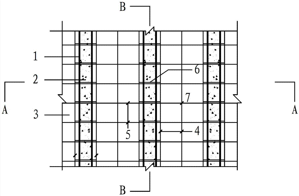
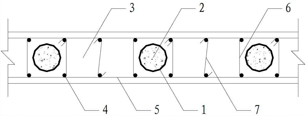
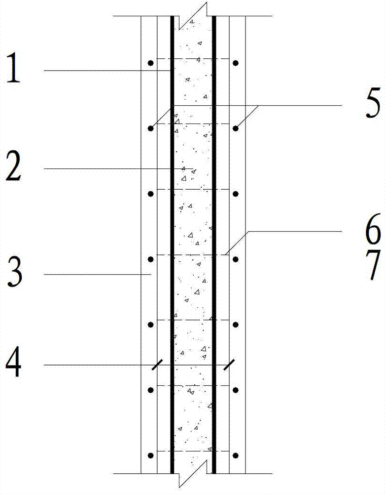
[0034] Such as figure 1 , figure 2 and image 3 As shown, a steel pipe concrete composite shear wall of the present invention comprises steel pipes 1 uniformly distributed along the cross section of the shear wall, steel pipe inner concrete 2 filled in the steel pipe 1, steel pipe outer concrete 3 poured outside the steel pipe 1, and arranged on Square stirrups 6 outside the steel pipe 1, vertically distributed reinforcing bars 4 and horizontally distributed reinforcing bars 5 arranged on the front and rear sides of the steel pipe 1, tie bars 7 tied between the steel pipe 1 and the vertically distributed reinforcing bars 4 and horizontally distributed reinforcing bars 5, and Longitudinal steel bars arranged at the position of the constraining members on both sides of the edge, the steel pipe 1, the vertically distributed steel bars...


PUM


Abstract

The invention relates to a concrete-filled steel tube combined shear wall and a construction process thereof. The shear wall comprises steel tubes which are distributed uniformly along the section of the shear wall, concrete filled into the steel tubes, concrete poured outside the steel tubes, square stirrups arranged outside the steel tubes, and vertically-distributed steel bars and horizontally-distributed steel bars which are arranged on front and rear sides of the steel tubes, tie steel bars which are tied between the steel tubes and the vertically-distributed steel bars and between the steel tubes and the horizontally-distributed steel bars, and longitudinal steel bars which are arranged at the positions of restraint members on edges of two sides of the steel bars. According to the concrete-filled steel tube combined shear wall, the steel tubes are embedded into the ordinary reinforced concrete shear wall, and the bearing capacity of the concrete is improved under the restraint action of the steel tubes, so that the sectional dimensions of the members are reduced, the dead weight of a structure is reduced, a seismic effect is reduced, and more usable areas are provided for buildings under the condition of the same design axial force; and anti-seismic properties of the flexural capacity, shear capacity, damage ductility and the like of the shear force are improved effectively by utilizing the high bearing capacity and high ductility of the concrete-filled steel tubes.

Description

technical field [0001] The invention relates to a shear wall and its construction process, in particular to a steel pipe concrete composite shear wall and its construction process. Background technique [0002] In recent years, with the continuous development of social economy and technology, high-rise and super high-rise buildings have been used more and more in cities. The continuous increase in building height puts forward higher requirements on the seismic performance of the structure. Reinforced concrete shear walls, as the vertical compression and key lateral force-resistant components in super high-rise buildings, are the first line of defense against earthquakes, and their seismic performance such as bearing capacity and ductility is crucial to the seismic safety of structures. Especially in the case of high structures and large vertical loads, the section design of the shear wall is often controlled by the axial compression ratio rather than the bearing capacity. I...

Claims


Application Information

Patent Timeline
Patent Type & Authority Applications(China)
IPC IPC(8): E04B2/56E04B2/64E04G21/00
Inventor 赵作周杨光钱稼茹
Owner TSINGHUA UNIV
Learn More