Light receiving subassembly

A sub-component, optical receiving technology, applied in electromagnetic receivers, coupling of optical waveguides, etc., can solve the problems affecting the signal quality of optical communication systems, and achieve the effect of improving optical communication quality and reducing optical energy.

Inactive Publication Date: 2013-01-30
SOURCE PHOTONICS CHENGDU
View PDF5 Cites 1 Cited by
  • Summary
  • Abstract
  • Description
  • Claims
  • Application Information

AI Technical Summary

Problems solved by technology

When the optical signal 17 is transmitted to the air 13 via the optical fiber, it is known from the calculation of Fresnel's equation that about 96% of the light energy 18 can penetrate the optical interface 15 of the optical fiber and enter the air 13, and about 4% ( The optical energy 19 of -14.4dB) is reflected back to the inside of the optical fiber 14, affecting the signal quality of the optical communication system

Method used


Image

  • Light receiving subassembly
  • Light receiving subassembly
  • Light receiving subassembly

Examples


Embodiment 1

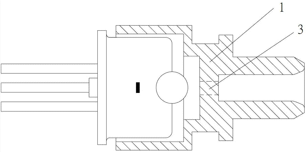
[0020] refer to figure 2 , the light-receiving subassembly listed in this embodiment includes a photodiode, a coupling lens, and an optical fiber connection sleeve 1. A through hole is provided on the optical fiber connection sleeve 1, and a filling block 3 is provided at the through hole. The filling block 3 is made of optically transparent material, and the filling block 3 is adapted to the through hole, that is, the filling block 3 and the optical fiber connection sleeve 1 realize seamless filling. Preferably, the filling block 3 and the optical fiber connection sleeve 1 are integrally formed by injection molding, which saves the process of assembling the filling block 3 and the optical fiber connection sleeve 1, and avoids the displacement caused by the filling block 3 and the optical fiber connection sleeve 1. The effect of reducing light energy returning to the optical fiber is not good. In addition, the filling block 3 and the optical fiber connection sleeve 1 are int...

Embodiment 2

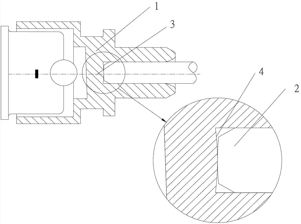
[0023] refer to image 3 , the light-receiving subassembly listed in this embodiment includes a photodiode, a coupling lens, and an optical fiber connection sleeve 1. A through hole is provided on the optical fiber connection sleeve 1, and a filling block 3 is provided at the through hole. The filling block 3 is made of optically transparent material, and the filling block 3 is integrally formed by injection molding with the optical fiber connection sleeve 1. The optical interface between the filling block 3 and the optical fiber 2 is the first optical interface 4, and the first optical interface 4 is a convex spherical surface, so that The contact between the optical fiber 2 and the first optical interface 4 is bump-to-bump contact, so that there is no gap between the optical fiber 2 and the filler block 3 (a gap means that there is air in the middle, which will reduce the transmission efficiency and increase the reflectivity), and reach the optical fiber. 2 is in the best co...

Embodiment 3

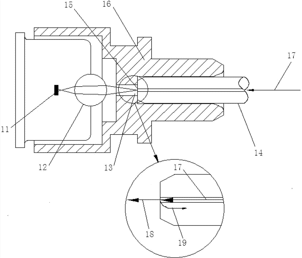
[0025] refer to Figure 4 The structure of the light-receiving subassembly listed in this embodiment is the same as that described in Embodiment 2, the difference is that the optical interface of the filling block away from the optical fiber is the second optical interface 5, and the second optical interface 5 is inclined plane. The light signal is reflected through the second optical interface 5 which is an inclined plane, which can further reduce the light energy reflected back to the optical fiber.


PUM


Abstract

The invention discloses an optical subassembly for receiving optical module signals. The light receiving subassembly comprises an optical fiber connecting sleeve for connecting optical fibers, wherein the optical fiber connecting sleeve is provided with a through hole; and a filling block made of an optical transparent material is arranged at the through hole and is matched with the through hole. According to the light receiving subassembly, the filling block made of the transparent material is arranged at the through hole of the optical fiber connecting sleeve, light passes through the filling block and is transmitted to the air, the refractive index of the filling block is close to that of an optical fiber, the reflectivity of the light back to the optical fibers through an optical interface where the filling block is contacted with the optical fiber is low, namely the optical energy returning to the optical fiber is reduced, and the optical communication quality is improved.

Description

technical field [0001] The invention relates to the field of optical fiber communication, in particular to an optical subassembly for receiving optical signals of an optical module. Background technique [0002] The role of the light receiving subassembly is to receive light signals and convert the received light signals into electrical signals. The structure of the commonly used light-receiving subassembly is as follows: figure 1 As shown, it includes a photodiode 11, a coupling lens 12, an optical fiber connection sleeve 16, and an optical fiber 14 is arranged in the optical fiber connection sleeve 16, and a through hole is provided on the optical fiber connection sleeve 16, so that the optical signal can pass smoothly and enter the light receiving subassembly . The optical signal 17 in the optical fiber 14 is transmitted to the air 13 through the through hole, and then the optical signal is coupled to the photodiode 11 through the coupling lens 12 . When the optical si...

Claims


Application Information

Patent Timeline
Patent Type & Authority Applications(China)
IPC IPC(8): G02B6/42H04B10/60
Inventor 陈宏源周一鸣傅钦豪粘志隆
Owner SOURCE PHOTONICS CHENGDU
Why Eureka
Try Eureka